Skip to content
Safran Logo
  • Products

      • Timing and Synchronization
      • GNSS Simulators
      • Atomic Clocks and Oscillators
      • Inertial Navigation Systems
      • Inertial Measurement Units
      • MEMS Accelerometers
      • Gyroscopes
      • NAVWAR
      • GPS Anti-Jamming
      • GPS Receivers
      • Emergency Locator Beacons
      • View All Products
      • SecureSync® Time Server
      • TimeLynx™
      • VersaSync Master Clock
      • White Rabbit Solutions
      • Scientific Instrumentation
      • PCIe Timing Boards
      • Skydel GNSS Simulation Software
      • Skydel GSG-7
      • Skydel GSG-8
      • Skydel GSG-8 Gen2
      • Skydel Anechoic
      • Skydel Wavefront
      • MIRA
      • SRO-100 Rubidium Atomic Clock
      • OCXOs
      • GPS Disciplined Oscillators (GPSDO)
  • Solutions

      • Aerospace
      • Custom Solutions
      • Data Centers
      • Defense
      • Finance / Fintech
      • Public Safety
      • Quantum
      • Space
      • View All Solutions
  • Learn

      • News
      • Use Cases
      • All Resources
      • Trade Shows and Webinars
      • Minerva Academic Partnership Program
      • Skydel Certification Courses
      • Skydel User Forum
  • Support

      • Support Hub
      • Professional Services
      • Support Packages
  • About

      • About Safran N&T
      • Orolia Acquisition Information
      • Product Compliance
      • Careers
  • en
    Speak To Support
    • Timing and Synchronization
      GNSS Simulators
      Atomic Clocks and Oscillators
      Inertial Navigation Systems
      Inertial Measurement Units
      MEMS Accelerometers
      Gyroscopes
      NAVWAR
      GPS Anti-Jamming
      GPS Receivers
      Emergency Locator Beacons
      View All Products
    • Aerospace
      Custom Solutions
      Data Centers
      Defense
      Finance / Fintech
      Public Safety
      Quantum
      Space
      View All Solutions
    • News
      Use Cases
      All Resources
      Trade Shows and Webinars
      Minerva Academic Partnership Program
      Skydel Certification Courses
      Skydel User Forum
    • Support Hub
      Professional Services
      Support Packages
    • About Safran N&T
      Orolia Acquisition Information
      Product Compliance
      Careers
    • EN
    Login

    STIM

    Support Hub for Safran STIM IMUs and MEMS Gyros

    FAQ
    Warranty Information Log a Ticket Leave Feedback
    View Map
    Application Notes

    Product Documents

    • 3D Model for STM277H, STIM377H, and STIM 380H

      Mechanical models of housing exterior.

      Learn More

    • 3D Model for STIM210, STIM300, STM318, and STIM320

      Mechanical models of housing exterior.

      Learn More

    • 3D Model for STIM 202

      Mechanical model of housing exterior.

      Learn More

    • Helium Sensitivity of Non-Hermetic STIM Products

      Learn More

    • STIM300 Centre of Mass Drawing

      Learn More

    • STIM300 Product Qualification Program

      Learn More

    • App Note: Timing Details Between Sampling and Datagram Transmission

      Learn More

    • App Note: Considering Sample Rates and Filter Settings

      Learn More

    • COTS for Space – Radiation Characterization of Gyro and IMU for LEO Operations

      Learn More

    • STIM Historical Production Data

      Learn More

    • Behavioral Performance During Vibration and Shock for a Tactical Grade IMU

      Learn More

    • High-G Testing of an Existing Tactical Grade Gyro Design

      Learn More

    • Technical Note: STIM300 Random Vibration “High Performance Aircraft”

      Learn More

    • TVAC Testing of STIM377H

      Learn More

    • Radiation Testing of STIM300 and STIM 210

      Learn More

    • Decoding of STIM Datagram, Programming Example

      This example only decodes STIM300 datagrams which fulfills the following requirements:Datagram contents: gyro output, accelerometer output and inclinometer output (Datagram identifier 0x93)Output unit, gyros: angular rate (output scaled for 400°/s gyros)Output unit, accelerometers: acceleration (output scaled for 10g accelerometers)Output unit, inclinometers: accelerationData starts at first byte of a datagram (i.e., datagram identifier) and contains only…

      Learn More

    • 32 Byte Calculation of CRC Checksum, Programming Example

      Learn More

    • 8 Byte Calculation of CRC Checksum, Programming Example

      Learn More

    • STIM Housing Material Thickness Measurements

      Learn More

    FAQ

    FAQ

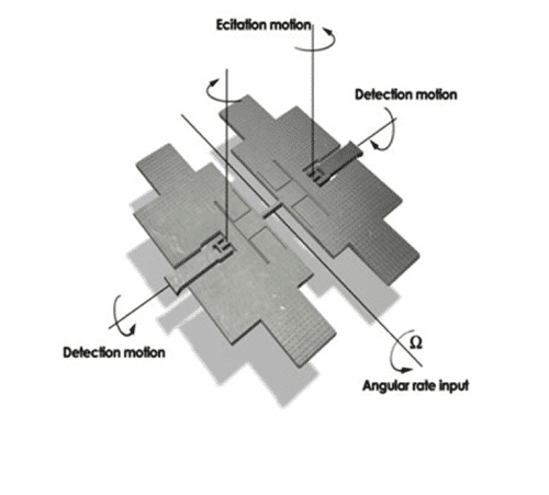
    • What is the principle of operation for gyros?

      We manufacture MEMS vibratory gyros based on the Coriolis effect. Below is a model of the Butterfly Gyro with two masses which are driven (excited) to oscillate at a resonance frequency close to 10 kHz. When a rotation of the gyro around the sensitive axis is applied, the two masses will deflect in a direction different to the oscillation. This is called the detection motion, which ultimately gives the angular rate sensed by the gyro.

    • Are the STIM products available without housing?

      No, the STIM gyros are mounted to the housings before calibration which is necessary for achieving the high performance they have. Housings cannot be modified.

    • Can STIM products be repaired?

      We can in some cases perform FW updates. The STIM products are not designed for mechanical repair.

    • Is a Certificate of Compliance (CoC) available for the STIM products?

      Our standard CoC is available with each shipment for customers that require this.

    • Is it possible to update STIM micro controller firmware?

      The STIM firmware can only be updated by our staff at our facilities.

    • Are the STIM products continuously temperature compensated?

      Yes, the gyros (as well as accelerometers and inclinometers where available) use internal temperature measurements to continuously compensate the output signal.

    • What is the “Time to valid data” for STIM products?

      This is the time needed from power-on or reset to clearing of the start-up bit (bit 6 in the status byte). During this period the output data should be regarded as non-valid. Details for each product is given by the product specifications.

    • What are the functional differences from STIM202 to other STIM gyro products?

      STIM202 is designed with internal mechanical dampers for operation in environments with shocks, e.g. direct mounting on remote weapon stations. STIM210 does not have mechanical dampers and also has twice as high data output rate compared to STIM202.

    • How is bias instability measured?

      Bias instability is measured by Allan Variance method, according to IEEE std. 952.

      Test is performed at room temperature (~25°C)

      Power is applied 2 hours prior to data collection

      Data are collected for 18 hours

      The root Allan variance is plotted and the bias instability is defined as the lowest point of the curve.

    • How is Angle Random Walk (ARW) defined?

      ARW is the white (random) noise of the sensor and is read from the root Allan variance curve at 1 second averaging time.

    • What type of low pass filters are used for STIM?

      STIM uses cascaded integrator-comb (CIC) low pass filters with linear phase response. Filter bandwidth (-3dB) is user configurable and can be set to 16Hz, 33Hz, 66Hz, 131Hz or 262Hz.

    • What is group delay?

      Group delay is the processing time of the signal through the low pass filter. The delay depends on filter bandwidth.

    • What is the TOV signal of STIM products?

      Time Of Validity (TOV) is for synchronization of datagram transmission with external events. TOV falling edge occurs synchronous to the sample rate. Raising edge occurs after last bit of datagram.

    • Can the STIM products output roll pitch and yaw in degrees?

      No, STIM does not operate as a standalone AHRS.

      The gyros can output angular rate, or integrated and incremental angle.

      The accelerometers can output acceleration, or integrated and incremental velocity.

    • What is the definition of Integrated angle?

      The integrated angle output is the angle since start-up or reset. The integrated angle is limited to ±4°, at which points a wrap-around occur.

    • What is the definition of Incremental angle?

      Incremental angle is the change in angle since the previous sample.

      E.g.: (100 °/s) / (125 sample/s) = 0.8°.

    • What is the accuracy of a position change measurement using STIM IMUs?

      STIM IMUs does not output position, but is used in several positioning systems.

      One of the leading GNSS/INS system builders obtain about 6 m horizontal position error after 60 seconds during a GNSS outage.

    • What is the resolution for the different accelerometer input ranges available for STIM300?

      2g: 0.5μg
      5g: 1.0μg
      10g: 1.9μg
      30g: 3.8μg
      80g: 15.3μg

    • STIM Evaluation kit: The indicator for “Data arriving from device” light is green but there is no output from the STIM.

      Verify that the bit rate settings of the computer serial port are in accordance with the STIM communication settings.

    • How to solve evaluation kit (EVK) error message “Unable to control supply voltage”?

      This error message occur when the EVK software don’t detect the startup datagrams. This happens when the STIM device is powered before the “Apply voltage” switch is flipped when connecting the STIM to the EVK SW.

      Disconnect the STIM and make sure the correct procedure is followed when connecting as described by the EVK user manual.

    • Do you have any example code for communicating with the STIM?

      We can help with examples e.g. for converting data bytes to angular rate measurements or how to calculate the cyclic redundancy check (CRC).

    • What is the CRC?

      The cyclic redundancy check (CRC) is a common way of making sure the data has been correctly transmitted – i.e. that the received data is identical to what was transmitted. The STIM calculates and output a check-number based on the contents of the transmitted data itself. The receiver will perform the same CRC calculation and compare to the received CRC to verify that the transmission was successful.

    Support Ticket

    Log Support Ticket

    Safran Federal Systems customers, please use this link for your support inquiries.

    Are you a distributor or reseller?
    Please list as many serial numbers as needed.
    Please tell us whatever you think would be relevant so we can best respond to your service and product support request
    Has the product been discovered to be missing, damaged, or not what you ordered upon delivery?*
    Has a failure been detected upon initial product usage?*
    Frequency of Failure*
    Reason for RMA*
    For RMA Return Requests
    For RMA Return Requests
    Video

    Tutorials

    Coming Soon.
    Follow us
    Safran Logo
    • Contact Us
    • R&D Projects
    • Privacy Policy
    • Code of Conduct
    • Terms and Conditions
    • Cookie Policy
    • Account Login
    Safran Logo

    Speak to Sales

    Complete the form, and our sales team will contact you within 1 business day.

    This field is for validation purposes and should be left unchanged.
    Name*
    This field is hidden when viewing the form

    Please submit ETL and PLB inquiries via the above links. Thank you. For inquiries and comprehensive details on Kannad Emergency Locator Transmitters (ELTs) and Sarbe Personal Locator Beacons (PLBs), please visit the Safran Electronics & Defense Beacons website: https://www.safran-group.com/companies/safran-electronics-defense-beacons/. For technical support, visit https://safran-navigation-timing.com/support-hub/kannad-elt/.

    Safran requires your contact information to provide details on products and services. You can opt out anytime. For more on unsubscribing and our privacy practices, see our privacy policy.

    For product support, please visit our support hub.