GSG Wavefront
SOFTWARE-DEFINED CRPA TEST SYSTEM
Protecting your GNSS systems from jamming and spoofing is more critical now than ever. This type of resilience is accomplished with an advanced GNSS Simulator capable of generating dedicated RF signals to test CRPA (Controlled Reception Pattern Antenna) architecture.
Safran’s GSG-Wavefront shared LO design (Shared Local Oscillator) is a field-proven “off-the-shelf” customizable and easy-to-use CRPA receiver testing platform. It provides an affordable and upgradable solution that leverages Skydel, its robust GNSS simulation engine built on a software-defined architecture.

CRPA are based on multi-element antennas designed to reduce the effects of RF interference, or establish signals’ angle of arrival. GSG Wavefront simulators emulate and generate the GNSS and interference signals as outputs of the antennas elements. The GSG Wavefront approach is different from classical anechoic CRPA Tester systems : it simulates the multi-elements antenna by providing as many RF outputs as antenna elements, to test the CRPA unit.
Advantages
Advanced Interference Generation Module
Generation of simple and complex interference signals is easy with Skydel’s “advanced jammers” module. Using a dedicated RF output of an SDR, interference signals can then be mixed to the GNSS signals. The interference can either be in-band or out-of-band and be composed of many waveforms of different power levels.
- Multiple virtual transmitters with user defined trajectories and waveforms
- User-defined waveforms (Chirp, CW, BOC, BPSK, AWGN & pulse modulations combination)
- Transmit arbitrary IQ data from file
- Dynamics are applied to transmitted signals
Scalable Architecture
The system architecture can scale up and down depending on the number of elements and signals, which dictates the number of GPU’s, computers, and so forth. The architecture starts with having simulator nodes. Each node corresponds to an element of the CRPA and is dedicated to simulating all the signals for that specific element. So, if you were to have a seven-element CRPA, you would use seven nodes to accomplish the simulation. Each node simulates the low power GNSS or “truth” signals, as well as the high-power signals such as jammers and spoofers. There are two different RF paths, which allows you to manage a huge dynamic range in power. Then the proper signals are sent to the RF distribution module at the bottom, where they are combined and brought to a specific element. The RF distribution module also provides a feedback loop to the simulator controller.
Signal “Store and Analyze”
With the Skydel GNSS simulator, it is possible to record the simulated GNSS and interference signals onto a disk in the form of digital IQsample files. This functionality can be very useful to analyze the generated signal with external post-processing tool (ex: Matlab). The analysis can be done directly on the baseband signal, avoiding impairments introduced by the up/down conversion to/from RF (ex: increased noise floor, phase noise of the oscillator, etc..).
CASE STUDIES
-
Safran to provide Becker Avionics with GSG-8 with fully operational SBAS function to test avionics receiver
Safran supplied a Skydel-based GSG-8 Advanced Simulator with advanced jamming and spoofing options to test the avionic receiver in real-life conditions.
-
GSG-8 and SecureSync Platforms Combined to Support GMV in the RIPTIDE Project
Discover how GMV utilized the GSG-8 and SecureSync platforms in the development of a robust PNT framework to limit the impact of GNSS vulnerabilities on maritime and inland waterways’ PNT applications within the Black Sea and Danube Lower Basin region.
-
Safran’s GSG-8 Advanced Simulator Drives R&D Testing for Stellantis (formerly FCA – Fiat Chrysler Automobiles)
Discover how the flexible and scalable GSG-8 platform delivered a cost-effective and high-end precision GNSS testing to the automotive industry.
REQUEST A QUOTE
FEATURES
- Scalable antenna configuration, supporting 2 to 16 multi-frequency antenna elements
- Modular all along the lifecycle
- Capable of supporting up to 4 GNSS bands simultaneously
- All GNSS bands : L1, L2, L5, E6, S band
- One GNSS output and one Interference output per antenna element. Combinable to have one RF output per antenna element
- Interference: Jamming, spoofing, and meaconing.
- Simulate multiple threats simultaneously
- Dynamic transmitters with user-defined waveforms
- Shared LO across all Software Defined Radios
- Continuous phase synchronization and alignment monitoring
- Real-time semi-automated calibration tool
- No specific calibration needed after power cycle
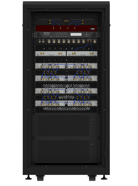
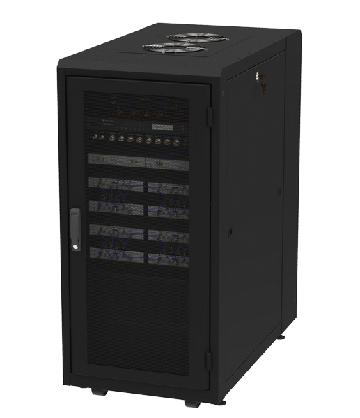
- Reduced form factor (24U rack for typical 8 elements system)
- Internal generation and distribution of low phase noise 10 MHz clock and 1-PPS signals
- (option) Rubidium low phase noise clock
- More information (Securesync 2400)
- Option: use an external clock, distribute the clock and PPS outside of the system and calibrate clock
- Hardware in the loop
- Quiet operation during simulation
- Powered by Skydel (with GUI & API)
SPECS
- Typical phase alignment bias: < ±1⁰
- Typical phase alignment deviation: 0.5° (1σ)
- Power accuracy on each element: ±0.5 dB
- Power alignment between elements: ±0,5 dB
- Simulation from cold start time: <90 seconds
- Up to 800 signals / element
- Iteration rate: 1kHz
- Dynamics:
- Maximum velocity: 1500 km/s
- Acceleration: no limits
- Jerk: no limits
- Jamming to GNSS Signal ratio: up to +130dB
- HIL latency under 10 ms
- GNSS constellations and Signals:
- GPS open services: L1-C/A, L1C, L1-P, L2-P, L2C, L5;
- GPS restricted signals: M and Y code
- GLONASS: G1, G2;
- Galileo open services: E1, E5a, E5b, E5AltBOC, E6 HAS,
- Galileo restricted signals: PRS
- BeiDou: B1, B2, B1C, B2A, B3I;
- QZSS: L1-C/A, L2C, L5
- NavIC: L1, L5, S-band
- SBAS L1 and L5: WAAS, EGNOS, MSAS, GAGAN, SDCM
- Custom Signals
- IQ reader
- Signal purity
- Spurious: <65 dBc
- Harmonics: <80 dBc
- Phase noise: <0.002 rad (RMS)

