Pico Second Timing for HEP (High Energy Physics)
Technical & Application Notes
ABSTRACT
One of the crucial elements of any scientific installation, especially in particle accelerators and laser ignition facilities, is the timing system.
Timing systems are used for providing a common notion of time to all the elements of the facility as well as for the generation of discrete triggering events and periodic signals needed by the various elements. In addition, it also can be used for radio frequency dissemination across the whole facility.
In this note, we present the timing system architecture currently under development by Safran for the distribution of synchronized triggers. The hardware, based on FPGA, is described. The system allows total flexibility when configuring the triggers in terms of direction, number of pulses, pulse rate, pulse period and delay.
Facilities are increasingly demanding better performance. The system proposed is intended to achieve high precision triggers with resolutions in the order of 5ps. The performance achieved will be shown in this work.
Hardware architecture used for the prototype
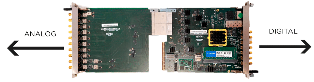
Timing Analog board
- SMA connectors:
- RF input for Fref: this signal is used to get the reference of the installation and to used it for synchronization with the installation itself.
- Up to 7 additional RF inputs to monitor RF signals
- Band pass filters in all the RF paths.
- Temperature sensor
- EEPROM memory
- Output amplifier in both channels
Performance Test/Results
ADC board (AMC digitizer controller)
- 10 x Analog to digital converters (ADC)
- 2 x Digital to analog converters (DAC)
- Zynq UltraScale+ FPGA from Xilinx
- PLL to generate internal clock signals
- 8GB DDR4 memory for processor and data storage (postmortem analysis)
- uTCA MMC stamp
- Temperature sensor
- uSD socket, uUSB port
- ETH & SFP port (White Rabbit compatible)
- EPICS compatible (control system)
Picoseconds Accuracy

Results:
Signal generation with an accuracy of a 3-15 picoseconds.
High accuracy signals can be generated with a delay of 3-15 picoseconds up to 1.8 nanoseconds compared to a reference PPS signal.
Images show a reference signal (blue) and another one delayed an amount of picoseconds (yellow).

Subnanosecond Synchronization

Results:
The Timing System integrate our HATI IP core, allowing for sub-nanosecond synchronization between a master (WR-Zen) and several slave devices.
The delay between PPS signals displayed in the image is maintained over time and can be calibrated to compensate cable delays.
Signal’s persistence of the capture is set to infinite to ensure that the jitter of the signals is visible if it is significative.
