# White Papers
Testing GNSS Receiver Resiliency Against Spoofing Attacks
Executive Summary
Spoofing as it applies to GNSS/GPS is an attempt to deceive the GNSS/GPS receiver by broadcasting signals that the receiver will use instead of the live sky signals. A test system for spoofing allows testing the three major factors to consider in a spoofing attack: time synchronization to the signals to be spoofed, power level of the spoofing signal compared to the live sky signals and accuracy of the position obtained by the spoofing signal to that of the actual position of the device being spoofed.
Receivers can provide some indication that something out of the ordinary is happening during a spoofing attack, but if the system that the receiver is integrated or embedded into does not monitor or attempt to use these indications, it is difficult to identify a spoofing attack. Understanding how a receiver will respond in a spoofing attack is the key to detecting spoofing. For example, it could be assumed by a system integrator that using multiple GNSS systems will prevent a spoofing attack consisting of only GPS. This is only true if the receiver is set up to monitor this type of information.
The spoofing test system allows full control over time synchronization, power level, and position variation in a completely closed system that will not interfere with actual GNSS signals. Each of these variables is described in detail and a sample of receiver test results presented. Test results include variations of time, power, and position and effects of varying these on three popular, widely-used GNSS receivers. Tests are performed using GPS only and also various combinations of GNSS systems (GPS, QZSS, BeiDou, Galileo, GLONASS) to understand if multi-GNSS is an effective method to overcome spoofing attacks. Using the information obtained by using a spoofing test system, a system using GNSS signals for navigation can fully utilize all information available to enable spoofing detection. Using a spoofing test system will allow a user to better understand the receiver and harden the system against spoofing attacks.
Introduction
Spoofing is different than jamming. Jamming is easier for a receiver to detect, and although it can disrupt the receiver, it cannot relocate it. A spoofing system can be used as an attack on systems that use GNSS for precise timing or navigation. A spoofing system can also be used for defensive research.
Research ongoing in the defense area on spoofing can be used to control an unmanned autonomous vehicle and redirect it. A spoofing test system can be used to understand how the receiver reacts in a spoofing situation and monitor and react to prevent the spoofing from occurring.
This paper describes the spoofing test system and how it is used to test receivers. Understanding the behavior of the receiver when faced with a spoofing attack is key to hardening the receiver against spoofing attacks.
Spoofing Test System
A spoofing test system can have two different configurations.
The first configuration is a live sky antenna used with one simulator and one synchronization system. The simulator is used to spoof the live sky signals in a controlled environment, but this test system quickly gets very complicated. It is hard to determine power levels and difficult to track a moving vehicle.
The second configuration is a full laboratory test system that consists of two simulators and one synchronization system. One simulator acts as the live sky signal and the other as the spoofer. It provides full control over time synchronization, power levels, and both positions. Using an Orolia GSG-8 or a combination of two Orolia GSG simulators with an Orolia SecureSync are two methods to understand the receiver in order to harden against spoofing attacks.
The test system used for the testing in this paper consists of two Orolia GSG simulators, one Orolia SecureSync, an RF switch, and an RF combiner. A PC is used to control the individual units, the RF switch and to monitor the receiver under test. Figure 1 illustrates this test system.

Parameters
There are several parameters that can be varied to help understand how vulnerable a specific receiver is to the spoofing threat. Each of these parameters can be varied independently of the other parameters allowing design of a comprehensive test plan. These parameters are Time, Position, and Power level. Figure 2 shows these parameters.
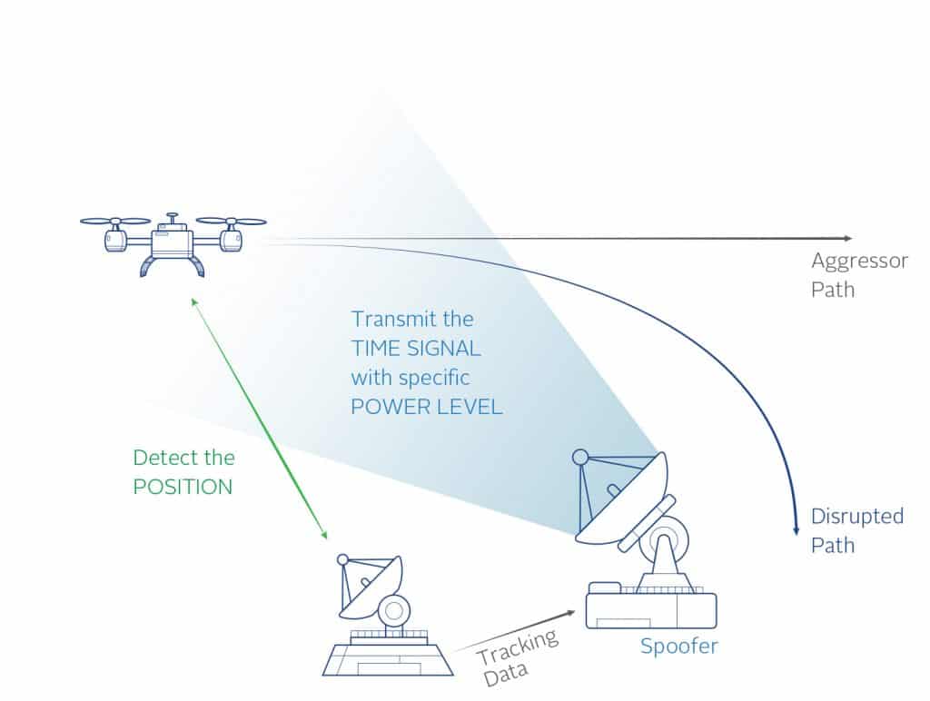
Figure 2: Important Parameters
Time
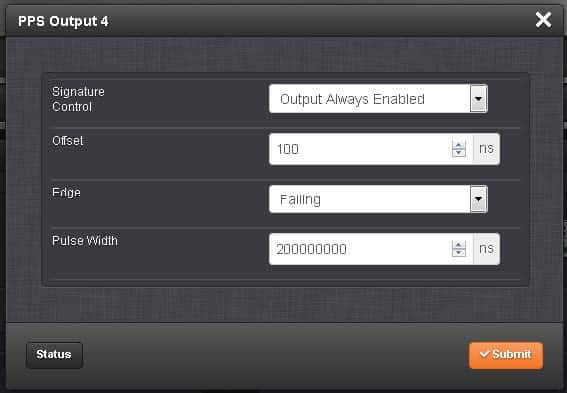
The timing accuracy of the spoofing signals to the live signals. Utilizing separate outputs from the SecureSync the PPS offset can be varied. These PPS signals are used as triggers to the GSG Simulator units and therefore cause an offset in time between the two RF signals. This offset is controllable to the nanosecond level.
Another time to consider in the test design is the capture time. This is how long the spoofing signal is applied before attempting to re-direct the receiver. Figure 3 shows the interface in the SecureSync for applying the offset.
Position
The position provided by the spoofer must be accurate to that of the receiver to be spoofed. Exactly how close the spoofer must be to the receiver position is a variable parameter
and can be different based on receiver settings, receiver manufacturer, and initial conditions (moving vs. stationary). Using two simulators allows full control of the two positions so
many different test cases can be designed and executed to understand the receiver limitations. The more accurate the spoofer must be to successfully take control of the receiver, the more difficult it will be for an attacker to spoof the receiver. Figure 4 shows an example of the two different positions with a 500m offset.

Figure 4: 500m Position Offset
Power
The spoofing signal should be greater than the live signal in order to capture the receiver. The spoofing test system allows full control of the power levels to determine how much greater the power should be. Too much power will jam the receiver. The test system allows testing of the receiver to try and determine if there are any indicators given by the receiver when a signal only a few dB higher than the transmitted signal is received.
Test Cases
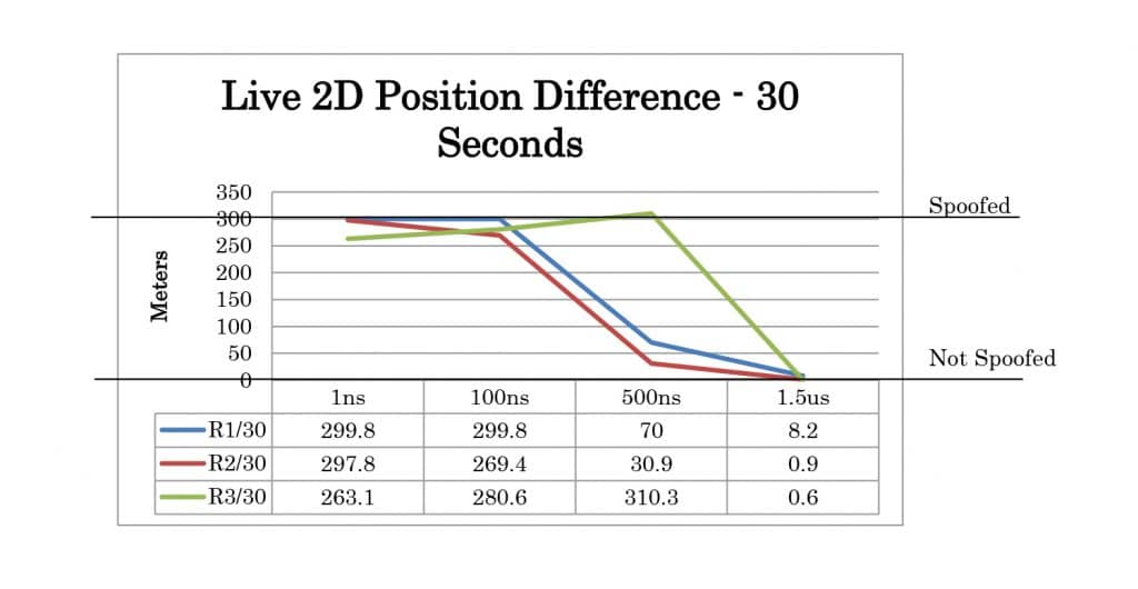
Several test cases were designed to observe the effects of varying the critical parameters and attempting to spoof the receiver. Four TIME offset test cases were created. For these cases, the position offset was 0 meters and the power level of the spoofer was 2dB higher than the live sky simulator. Offsets of 1 nanosecond, 100 nanoseconds, 500 nanoseconds, and 1.5 microseconds were tested.
Three POSITION offset test cases were created. For these test cases, the time offset was set to 1 nanosecond and the power level of the spoofer was 2dB higher than the live sky simulator. Offsets of 50 meters, 250 meters, and 500 meters.
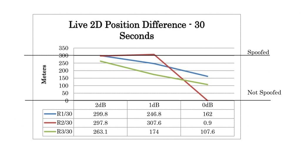
Three POWER offset test cases were created. For these test cases, the time offset was set to 1 nanosecond and the position offset is set to 0 meters. Offsets of 2dB, 1dB, and 0dB were tested.
Finally, there was a test created for multi-GNSS. In this case the live sky simulator was set to simulate GPS and GLONASS. The spoofer was set to GPS-only. The position offset was set to 0 meters, the time offset was set to 1 nanosecond, and the power level of the spoofer was 2dB higher than the live sky simulator.
Figure 5 shows the test cases.

Test Execution
The test set up was configured to execute the following sequence:
- T=0 Start Automated Test Scenario
- Live Sky Only (static position)
- Spoofer is not switched in
- ∆T=3min Enable Spoofer
- Combine Live Sky with the Spoofer set to the starting position
- Spoofer is automatically switched in
- ∆T=5sec Initiate Spoofer Trajectory
- Spoofer position begins to change via GSG Simulator predefined scenario:
- 90 degree heading; 10m/s speed
- Allows a 5 second capture time
- Spoofer position begins to change via GSG Simulator predefined scenario:
- ∆T=30sec and ∆T=60sec Automated Data Measurement
- Results from receiver’s reported position are logged for analysis
Using this sequence tests can be performed in a repeatable and consistent manner, helping to understand the receiver and how its performance is effected when a spoofing attack is attempted.
Test Results
Three receivers were used to perform the test cases.
- Septentrio AsteRx3 OEM Receiver (R1)
- Ublox NEO-M8N (R2)
- Inventek USB-GPS / SiRFstarIII (R3)
The test results can be analyzed by comparing the logged positions from the receiver at 30 seconds and 60 seconds after the movement has started. The results summary for 2D position is shown in Table 1. Each case is categorized as not spoofed, partially spoofed, or fully spoofed. Not spoofed (No) means the position did not change from the live sky position. Partially spoofed (P) means the position was changed but was not that of the live sky simulator or the spoofer. Fully spoofed (Yes) means the receiver position was that of the spoofer. N/A indicates mode not available in the receiver.
Full test results are given in Appendix A. At 30 seconds the spoofer 2D position is 300 meters away from the live sky position. At 60 seconds, it is 600 meters away. The altitude of live sky and spoofer position remains the same, so any deviation from 0m is due to the spoofing signals.
Table 1: Test Results Summary
| R1 | R2 | R3 | ||
|---|---|---|---|---|
| TIME | 1ns | Yes | Yes | Yes |
| 100ns | Yes | Yes | Yes | |
| 500ns | P | P | Yes | |
| 1.5us | No | No | No | |
| POSITION | 50m | Yes | Yes | Yes |
| 250m | Yes | P | P | |
| 500m | P | P | P | |
| POWER | 2dB | Yes | Yes | Yes |
| 1dB | Yes | Yes | P | |
| 0dB | P | No | P | |
| MULTI-GNSS | Multi-GNSS with GPS Spoof |
No | No | N/A |
Phase Compensation
The spoofing test system can also be adapted to use in live over the air spoofing scenarios at special test sites. When attempting to spoof a live moving vehicle it is important to also
consider the phase shift in the signal as it travels from simulator to the vehicle to be spoofed. The GSG simulator can be commanded to compensate for this distance by utilizing a
clock model built into the simulator. This time of flight compensation can be commanded using a SCPI command when the GSG has the spoofing option enabled.
Conclusion
The Spoofing Test System allows for better characterization through systematic repeatable tests of receiver performance in the presence of a spoofer. By monitoring the available
parameters given by the receiver it may be possible to identify and even overcome a spoofing attack. Monitoring loss of lock, receiver noise, IMU system, and estimated position error are
possible parameters to observe but each receiver may report different indications. Receivers may also have different modes of operation to test and observe the results.
Appendix A
Time Offset Results
