Adding Jamming and Spoofing to a GNSS Simulation
Tutorial
LINK FOR THIS SCENARIO | GITHUB
GSG-8 is the newest positioning, navigation, and timing test solution offered through Orolia’s GSG family of simulators, and powered by Skydel Simulation Engine. It was developed to deliver the highest standard of Global Navigation Satellite System (GNSS) signal testing and sensor simulation performance in an easy to use, upgradable and scalable platform.
This document explains how to implement advanced jamming with Skydel.
1.1. Hardware configuration / Licenses required
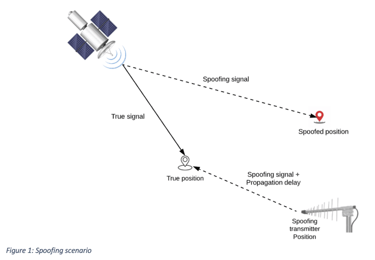
Spoofing consists of faithfully recreating the signals from several satellites, then transmitting this “spoofing” signal to capture a local GNSS receiver (Figure 1). If the targeted GNSS receiver is unable to differentiate between real satellite signals and spoofed signals, the spoofing will trick the target receiver into believing it is in a different location.
For this simulation, we are going to place our vehicle at a fixed position in the center of the Eiffel Tower. Next, we will place our spoofer on a fixed boat 240 m from the vehicle. We will also add a jammer with a circular trajectory with a radius of 150 m.
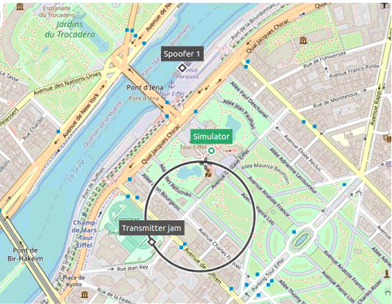
Our goal by spoofing the receiver, is that it loses the true position of the simulator which is fixed and that it follows a wrong direction which is the trajectory described below.
The GSG-8 hardware models that can be used to run this simulation are:
| GSG-821 | GSG-831 | GSG-842/Broadsim |
|---|---|---|
| 2 RF Outputs | 3 RF outputs | 4 RF outputs |
| 1 GPU/2 SDR | 1GPU/3 SDR | 2 GPU/4 SDR |
To be able to carry out this scenario, the SKY-ADVSP and SKY-ADVJAM option must be activated in the Skydel simulation.
For this study case, we will illustrate a simple scenario of implementing spoofers with Skydel.
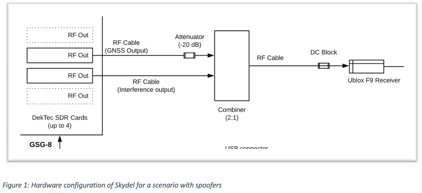
Here is the hardware configuration used for this scenario:
1.2. Software configuration
To achieve advanced spoofing in Skydel, at least two instances are required:
The truth instance, which manages the truth signal, the true position and the spoofing transmitter position.
The spoofing instance, which manages the spoofing signal and the spoofed position.
NOTE: This step is only necessary to add additional radios; a first radio will be preconfigured on your default configuration. Multiple setup options are possible; refer to the main Skydel manual for more information.
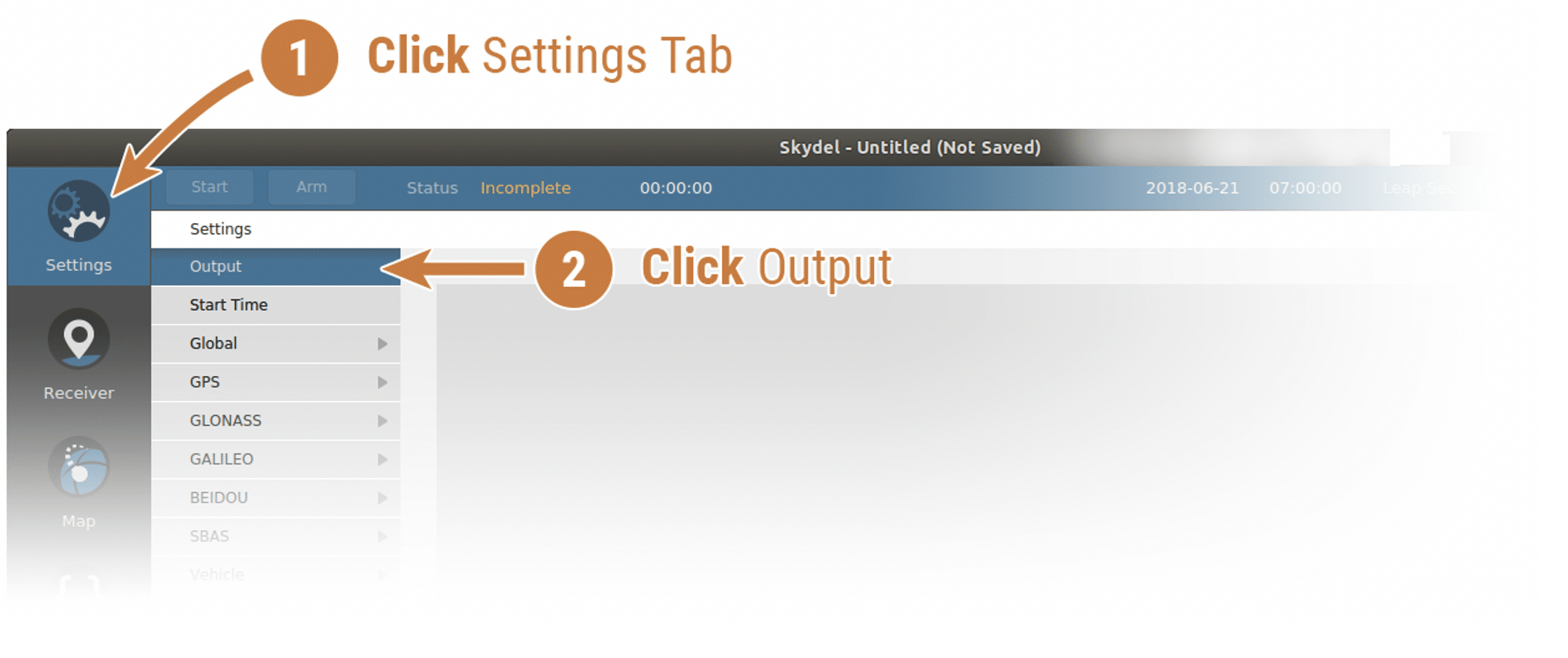
To add a radio, navigate to Settings – Output.
Select the DTA-2115B in the dropdown list and click the Add button twice.
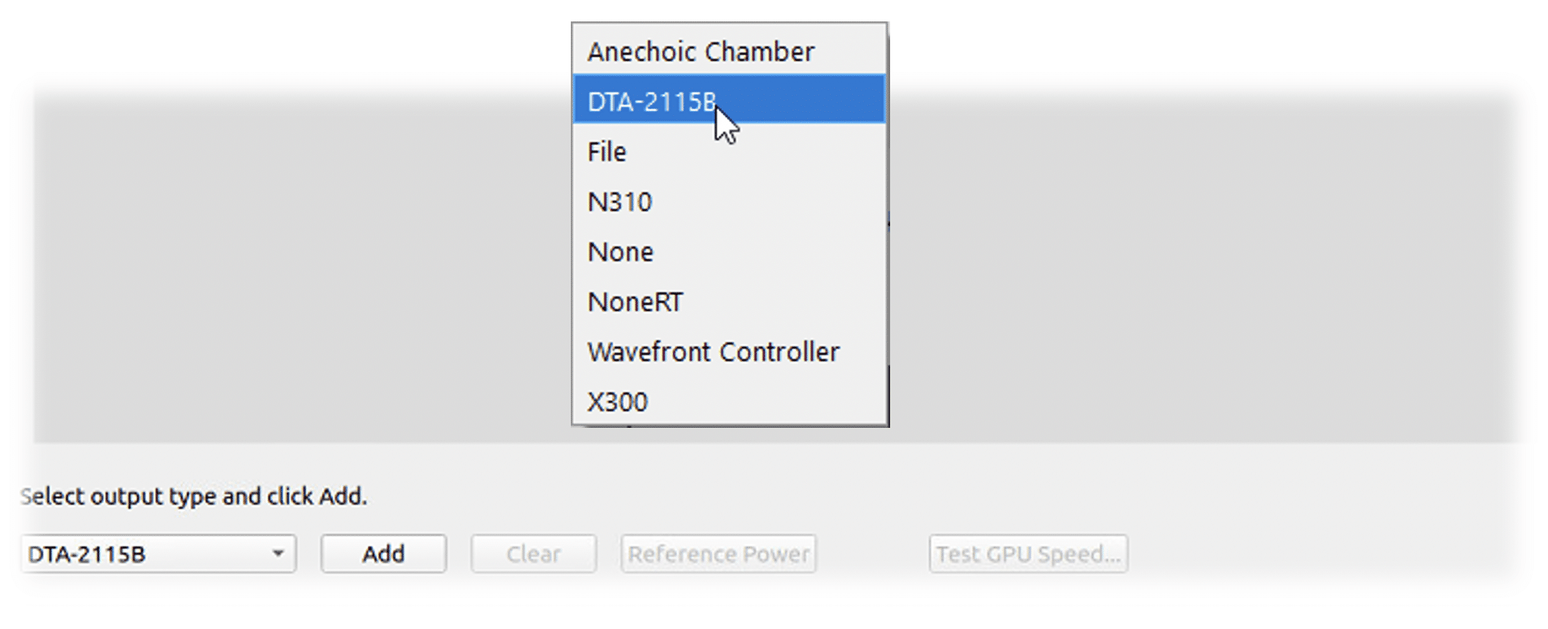
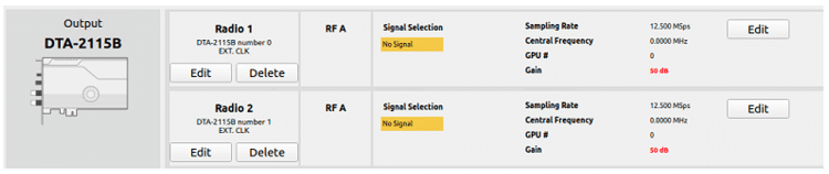
The DTA-2115B will be added with a default device number 0 and default clock settings. If the default values are incorrect for your hardware setup, click Edit to make the necessary changes and click OK when done.
Select GNSS Signals
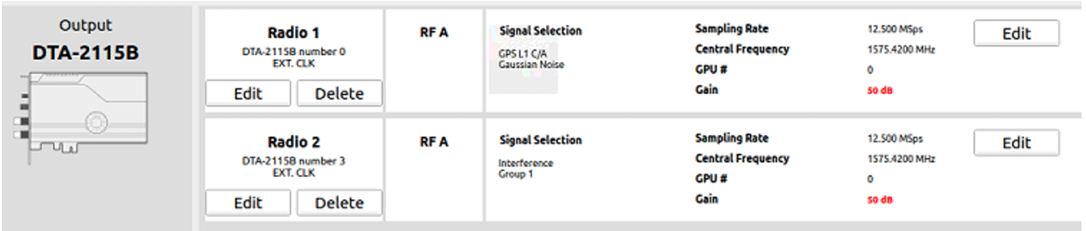
Click the Edit button for the RF A output of Radio 1, select GPS L1 C/A and check Gaussian noise.
Then click Edit on RF A output of Radio 2 and then select interference/Spoofer in the Output type.
Choose Group 1 and select Choose with signal selection.
Change the gain to 30 dB and the minimum sampling rate to 12.5 MSps.

Click Ok to close the Signal Selection dialog box. The output configuration should look like this:
Then go to the vehicle tab to define the simulated true position.
Select fixed for the trajectory and enter the following coordinates:

Add dynamic transmitter (jammer)
The next step now is to add a transmitter. Indeed, we add the transmitter because in some cases, it would first be necessary to jam the receiver to disturb it for a while and then activate the spoofer. Thus, the receiver can easily pick up the signal from the spoofer.
First, click on the Settings – interference submenu.
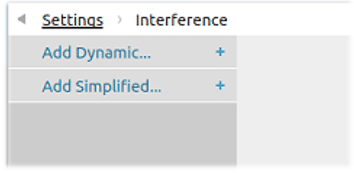
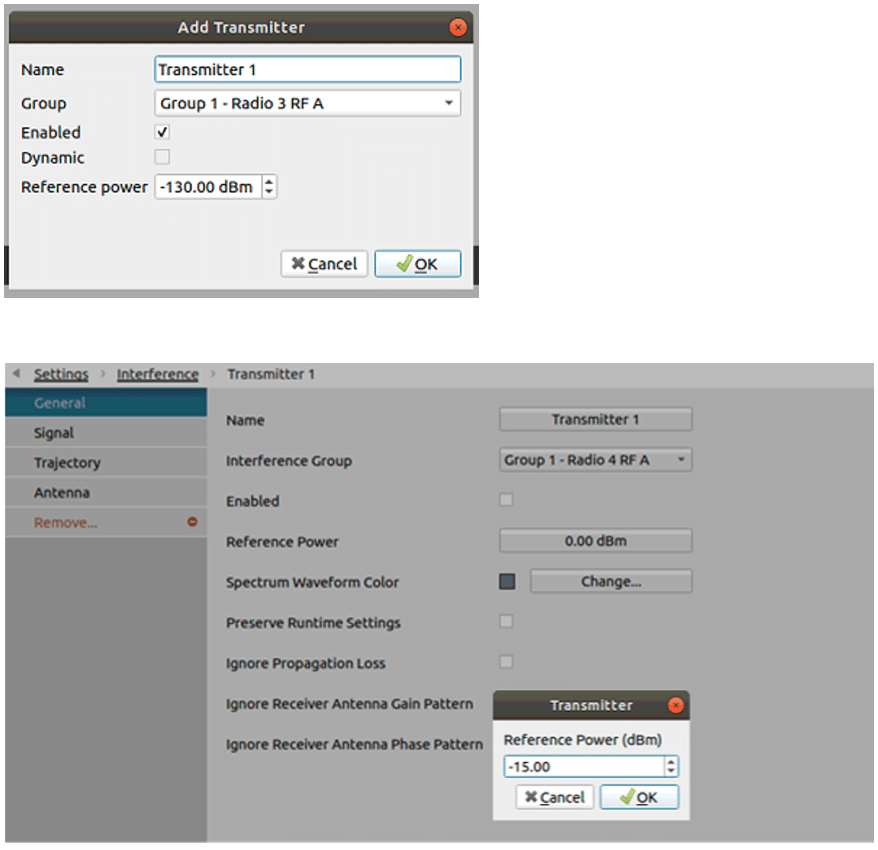
Click on Add Dynamic… and the Add Transmitter dialog box will appear.
Click the Trajectory button to display the transmitter trajectory page screen. Define the circular path with the following attributes:
- Center: 48.85699094 degrees north, 2.29621810 degrees west, 2 m above sea level.
- Radius: 150 m
- Speed: 10 m/s
- Motion: counterclockwise

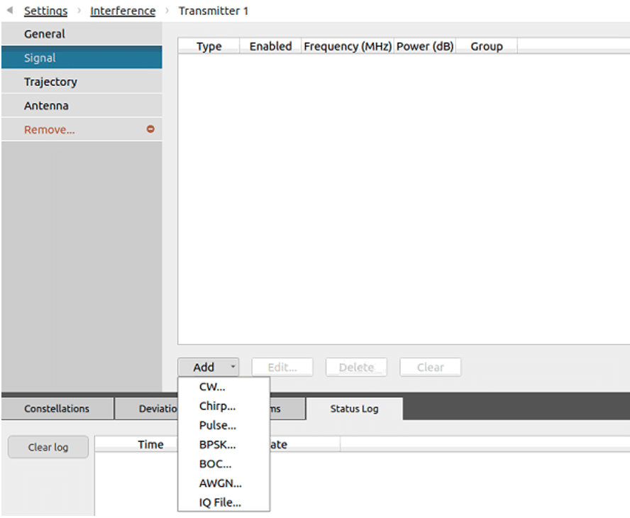
Now we can add the signal that will be transmitted by the jammer.
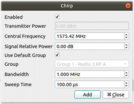
Let’s add a Chirp signal. To add this signal, click Add on the Signal button.
When the chirp signal window opens, change the center frequency to 1575.42 MHz, which corresponds to that of the GPSL1 CA.
Add a spoofer
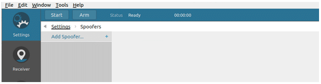
When the Advanced Spoofing feature is activated, you will see a new tab called Spoofers.
To add a spoofing transmitter, go into this tab and click on Add Spoofer.
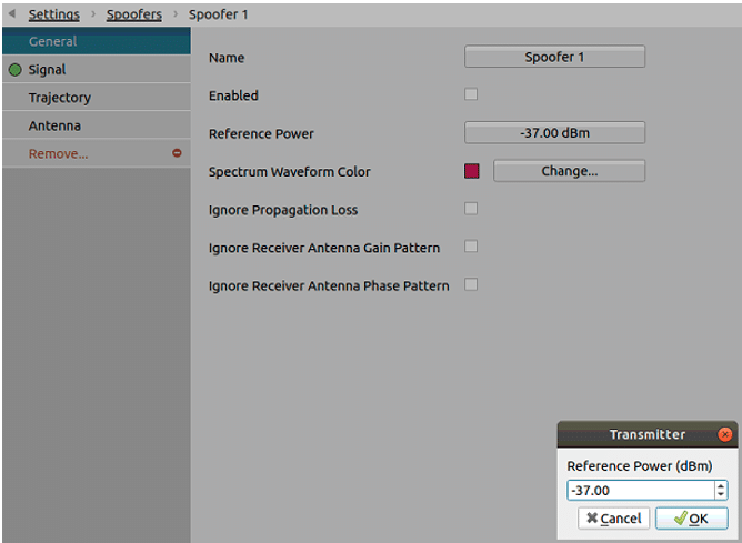
Then click on the general button of the spoofer window. Then set a value of -37 dBm for the Reference Power and click on Enabled to deactivate the spoofer.
Click the Trajectory button to display the spoofer position page screen. Select fixed with the following parameters:
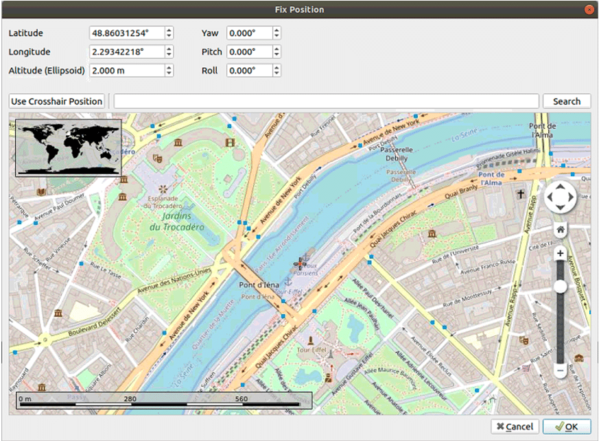
The spoofer parameters are now configured. The next step is to define the spoofing signal, transmitted by the spoofer.
To start a spoofing instance, search for the shortcut Skydel Spoofer on your operating system or start the application in a command line shell with the –spoofing argument.
This instance is almost the same as a regular instance, with the following exceptions:
- There is only one type of output: Spoofer.
- The Spoofer output is assigned to an interference group that will be used in the main instance.
- Only GNSS signals can be configured. These are the definition of the spoofing signal.
- The Vehicle section defines the spoofed position.
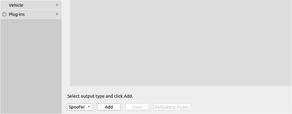
Open the spoofer instance and select new configuration:

Click Add Spoofer to add a spoofer output.
Then click on edit to add a signal to the spoofer.
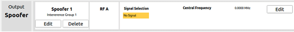
Then select GPS L1/CA in the Signal Selection.


Then go to the vehicle tab and select circular in the trajectory selection.

Add and configure a receiver
Let’s start the simulator now and connect a receiver in order to view the simulator, the receiver, and the transmitter in the map tab.
The receiver we used for this example is a U-Blox receiver.
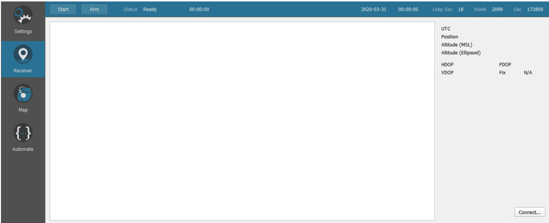
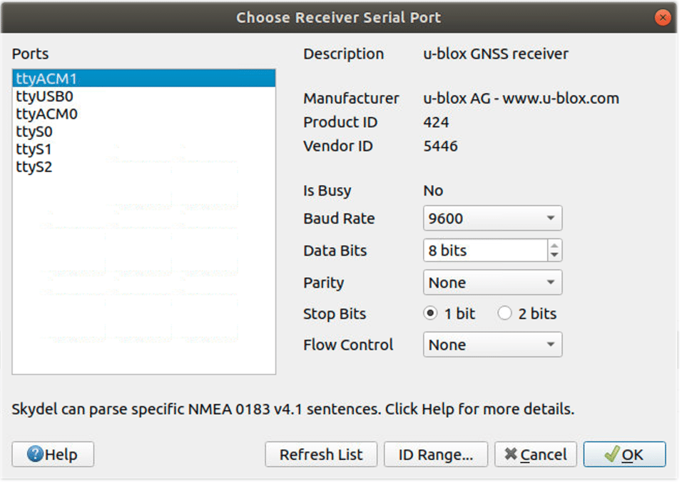
To configure it, go to the Receiver window of Skydel and click on connect.
Now select your receiver Serial port in the Choose Receiver Serial Port window:
Run the simulation
Click on the Skydel map tab:

If you open the transmitter information panel to the right of the map, you will see that the jammer and the spoofer are not activated.

In the spectrum subtab, you will see that the GPS signal is being transmitted on the radio 1 RF A.

In this example, we will directly activate the spoofer with no intermediary jamming. Some receivers and configurations may need to be jammed to lose the true GNSS signal, before activating the spoofer.
Now, go to the Transmitter’s General screen and enable the transmitter. You should now see the spoofed signal appearing in the RF B spectrum.
Transmitter 1 is now activated and can be seen appearing in the second window of the spectrum.
We can see that the receiver is fixed at the position of the simulator.
When we then activate the transmitter, we immediately perceive that the receiver begins to be affected.

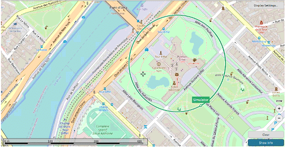
We see after a few minutes the effect of spoofing on the receiver which begins to pick up the false signal from the spoofer.

After some time, we can see that the receiver is completely spoofed and follows the wrong direction imposed by the spoofer.

Conclusion:
In this application note, we have demonstrated how to easily set up a spoofing scenario with a GSG-8, and test the resilience of a receiver. From this simple Skydel scenario, even more advanced use-cases can be defined, with more jammers, spoofers, and complex attacks. These advanced scenario are easily configured with Skydel with less equipment required, compared with traditional simulators, where such scenarios are more complex, if not impossible.