Real Time Correction Messages (RTCM) Plug-In
Technical & Application Notes
Introduction
This document is an application note for using the Real Time Correction Messages (RTCM) plug-in with the Skydel Simulation Engine.
RTK
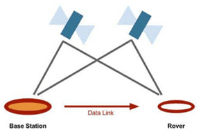
Real-time kinematic positioning (RTK) is the application of surveying to correct for common errors in current satellite navigation (GNSS) systems. RTK positioning is based on at least two GPS receivers—a base receiver and one or more rover receivers.
The base receiver takes measurements from satellites in view and then broadcasts them together with its location to the rover receiver(s). The rover receiver also collects the satellites’ measurements and processes them with the base station data. The rover then estimates its location relative to the base.
The GNSS carrier phase signals are key to achieving centimeter-level positioning accuracy with RTK. Carrier phase measurements are like precise tape measurements from the base and rover antennas to the satellites. In the receiver, carrier phase measurements are made with millimeter precision. Although carrier phase measurements are highly-precise, they contain an unknown bias called integer cycle ambiguity or carrier phase ambiguity. The rover must resolve, or initialize, the carrier phase ambiguities at power-up, and every time the satellite signals are interrupted.
RTK technique is adopted by many modern GNSS receivers and support the RTCM 3.3 standard.
RTCM 3.3 (also known as RTCM 10403.3, differential GNSS services – version 3) is a standard developed by The Radio Technical Commission for Maritime Services that describes the protocol for the transmission of differential corrections data allowing GNSS receivers to calculate their position with higher precision.
The data contained in RTCM 3.3 messages include carrier phase and pseudo-range measurements made by a base station. The base station is a GNSS receiver that processes GNSS signals like the usual receiver, but its position is known in advance with outstanding precision. RTCM 3.3 data being transferred from the base station to another GNSS receiver (“rover”) allow that receiver to compensate for its measurement errors and thus improve its positioning precision.
Reference: A preliminary reading is in the user manual.
Skydel RTCM Plug-In User Manual
1. RTCM use case: Using Skydel RTCM Plugin
1.1. Hardware Setup
The GSG-8 hardware model that can be used to test the RTK plugin are:
| GSG-811 | GSG-821 | GSG-831 | GSG-842 |
| 1 RF Output 1 GPU/SDR | 2 RF Outputs 1 GPU/2SDR | 3 RF Outputs 1 GPU/3SDR | 4 RF Outputs 2 GPU/4 SDR |
BroadSim can also be used; it has the same configuration as a GSG-842.
For this case study, we will show a simple scenario of using the RTCM Plugin with Skydel.
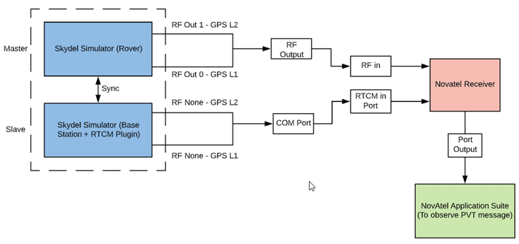
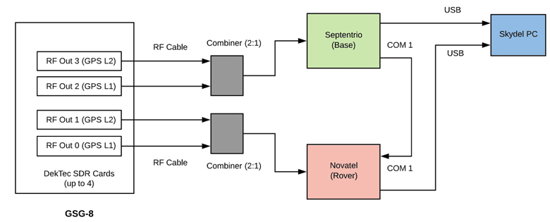
In Figure 1 below is a block diagram showing the system configuration. RF0 and RF1 are combined using a combiner, DC block, and 20 dB attenuator, as shown in the GSG-8 Getting Started Guide. Both the master and slave instances of Skydel are running on the same GSG-8 unit. In this application note, we configure the L1/L2 signals. But it is not mandatory to be dual-frequency for RTK. Users can choose L1 frequency using only GSG-811.
1.2. Software Setup
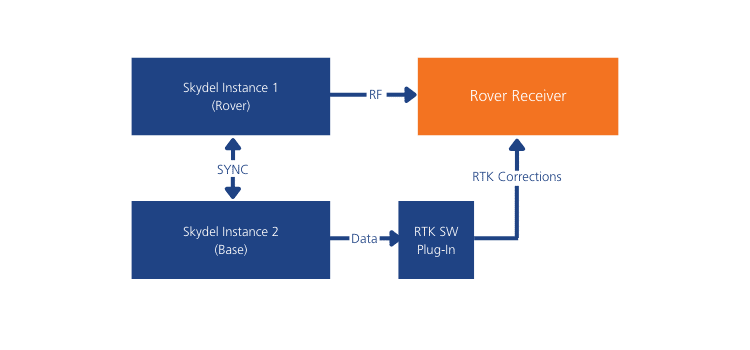
Two instances of the Skydel application are required to simulate GNSS constellations for both the base station and the rover. The rover instance uses the RF outputs connected to the rover receiver under test. The instance used for the virtual base station simulation can be configured to use “NoneRT” output.
1.2.1. Base station configuration
Open a Skydel instance and start a new configuration. Navigate to Settings – Output:

1. Signal selection
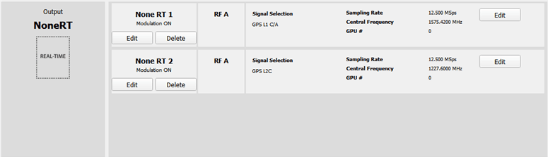
In Settings -> Output, select “NoneRT” output and click Add twice. Choose the signals you want to simulate for the base station in the output settings.
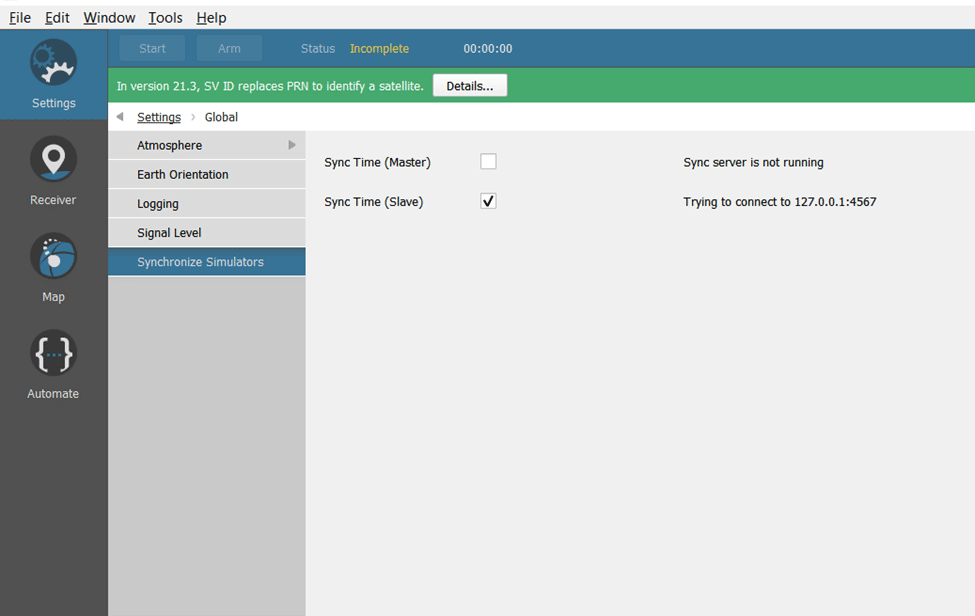
2. Time synchronization with the base station
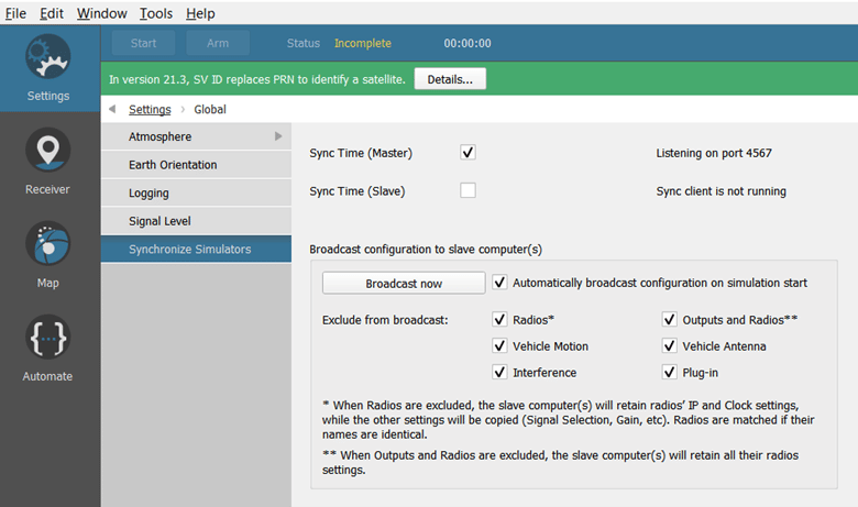
Allow base station simulator to be synchronized with the rover simulator. Go to Settings -> Global -> Synchronize simulators. Set checkbox “Sync Time (Slave).” This will allow both instances to start at the same time.
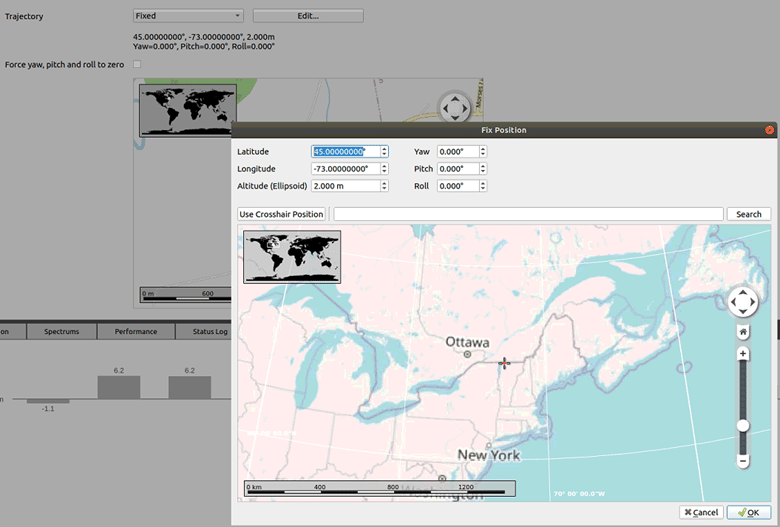
3. Vehicle trajectory
Select base station position in Settings->Vehicle->Body.
Set trajectory type to “Fixed” and enter the coordinates as shown in the image:
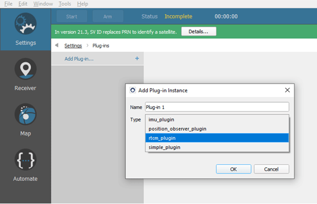
4. RTCM configuration
Load RTCM plugin into configuration. Go to Settings->Plug-ins and select Add Plug-in. Set the name and type of plug-in instance and select Ok:
Select the new plug-in instance:

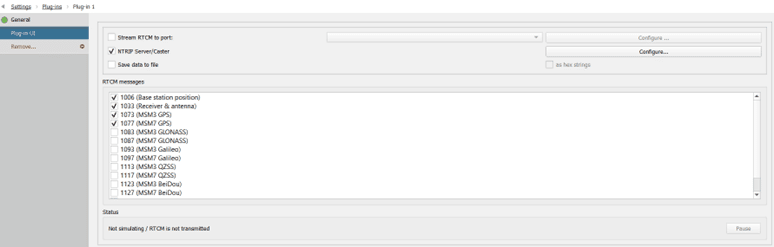
The Plug-in UI menu displays the plugin’s interface.
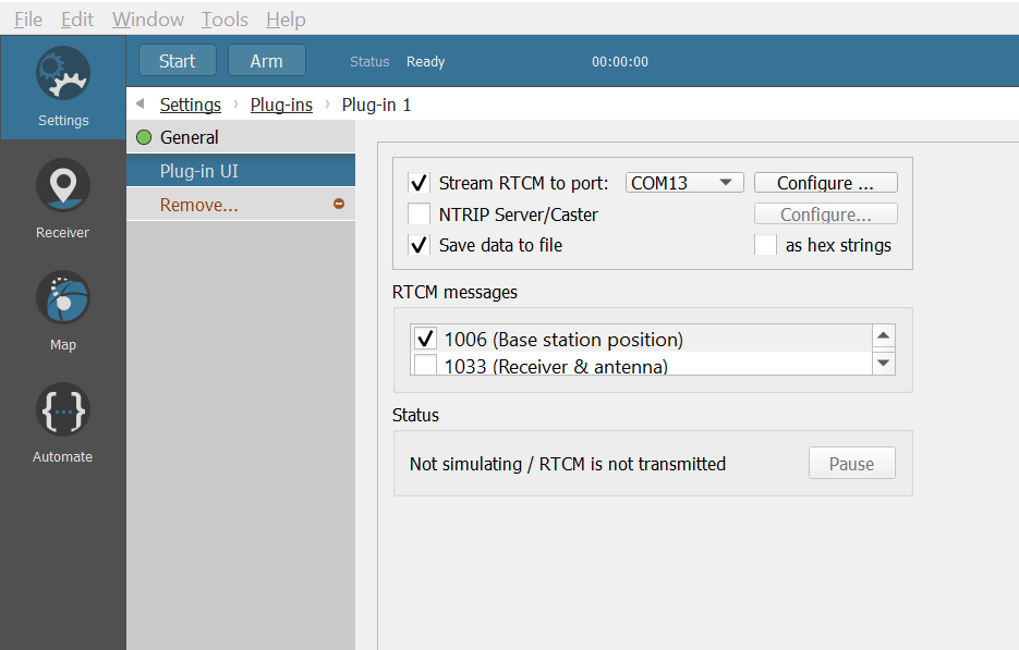
The “Stream RTCM to port” line allows you to select the serial port used to broadcast the RTCM data. A PC serial port must be physically connected to the receiver. Ensure the communication parameters (under the “Configure” button) match the serial port parameters on the receiver side. Remember that the selected baud rate should be sufficient to broadcast all selected messages in real-time. Usually, 115200 is a good choice.
In the menu RTCM messages, the messages selected for this scenario are:
- ⇒1006 (Base Station position)
- 1073 (MSM3 GPS)
Save your configuration.
1.2.2. Rover configuration
Open a Skydel instance and start a new configuration.
1. Signal selection
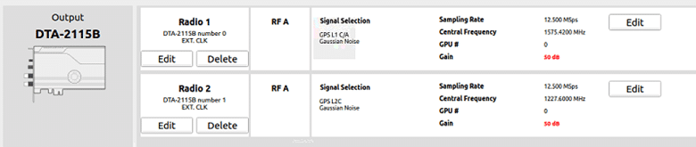
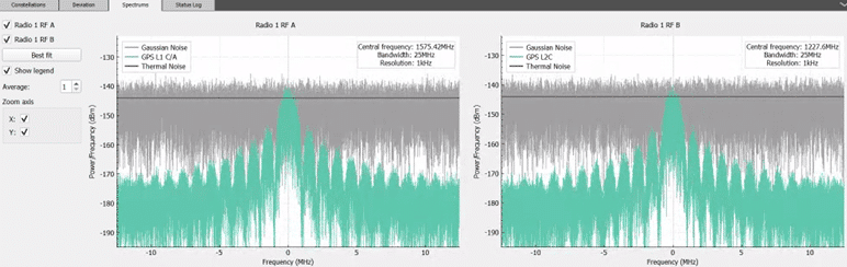
Click the Edit button for the RF-A output of Radio 1 and select GPS L1 C/A and GPS L2C for Radio 2.
2. Time synchronization with Rover
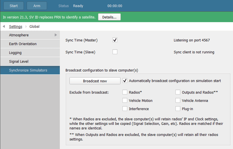
Allow rover simulator to be synchronized with base station simulator. Go to Settings -> Global -> Synchronize Simulators. Set checkbox “Sync Time (Master).”
This will allow the base station simulation to start with the rover simulation. Set checkbox “Automatically broadcast configuration on simulation start.” Exclude “Radios,” “Outputs and Radios,” “Vehicle motion,” “Vehicle antenna,” “Interference,” and “Plug-in” from synchronization.
3. Vehicle trajectory
Select rover trajectory in Settings->Vehicle->Body
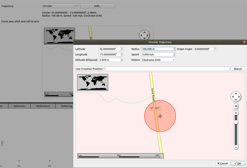
Set trajectory type to “circular” and enter the coordinates as described in the image:
Save your configuration.
To demonstrate the feature, we will use the Novatel OEM7700 receiver. If your receiver is different, please install and configure the receiver according to the manufacturer’s instructions.
1.2.3. NOVATEL Receiver
1. Install Novatel Application Suite
NovAtel Application Suite runs on a Windows® 10 computer and communicates with the Novatel receiver using a serial, USB or Ethernet connection.
To install the NovAtel Application Suite, download the NovAtel Application Suite installation file from the NovAtel web page: https://novatel.com/products/firmware-options-pc-software/novatel-application-suite
Follow the wizard to install the NovAtel Application Suite.
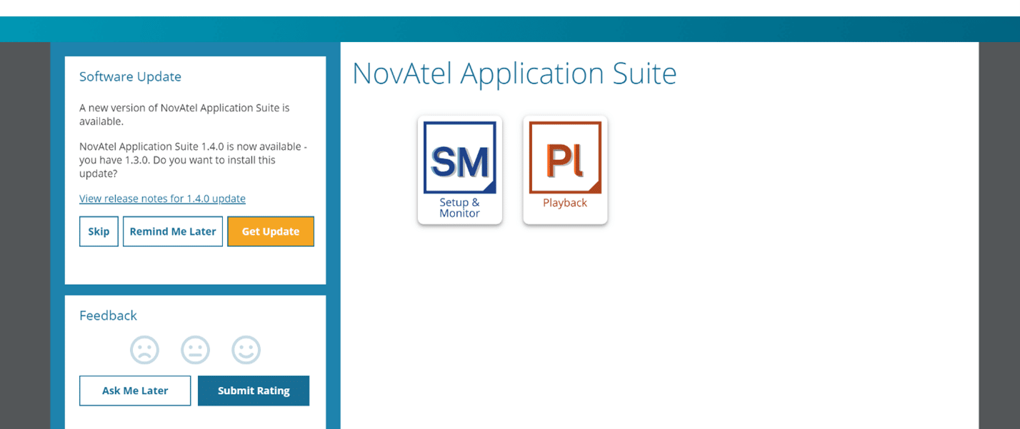
2. Start Novatel Application Suite
Open the app and click on the Setup Monitor (S&M) icon to start.
3. Add a Device – USB Connection
Before a Setup & Monitor session can be started with a receiver, a Device must be added for the receiver on the Devices window.
Click the Add Device button. The New Connection dialogue box opens:
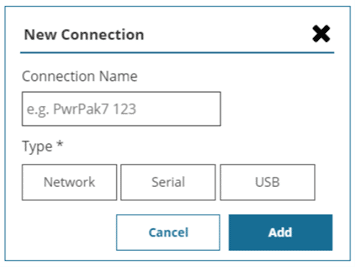
In the Connection name box, type a name for the device.
Click the USB button. The New Connection dialogue box expands to display the USB settings.
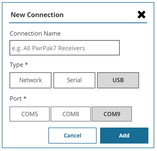
Click the button on the virtual COM port you used for this receiver.
Click on the Add button. A new device labelled with the name entered in the Login name box is added to the devices window.
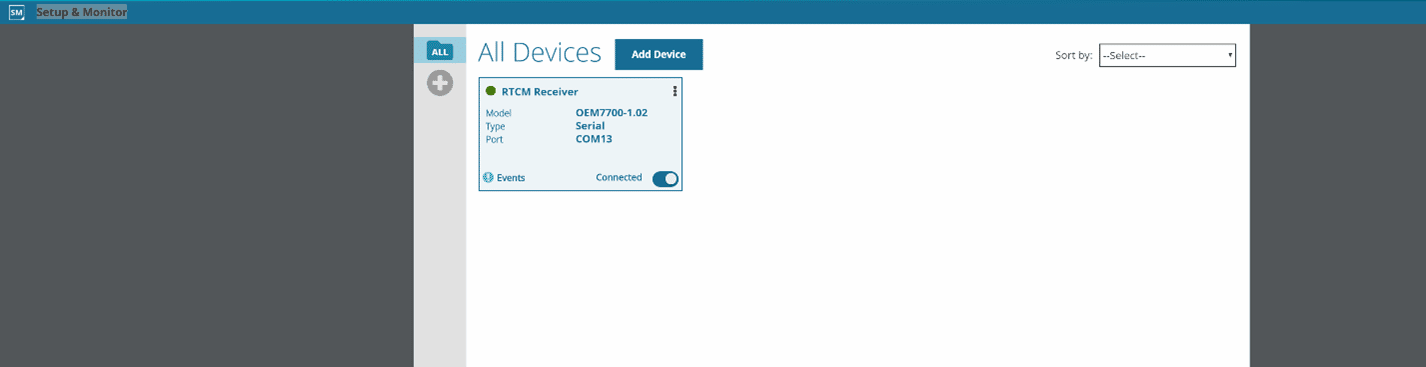
4. Status and Configuration Window
When a connection to a receiver is opened, the Status and Configuration window is displayed. All of the status and configuration windows for the receiver can be accessed from this window.
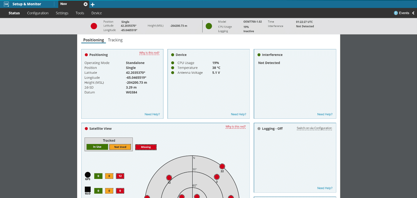
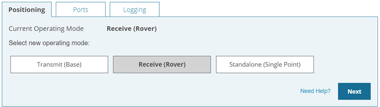
To set up your Novatel Receiver in the RTK mode, go to the Configuration menu and select the Positioning window.
Check Receive (Rover) and click on next.
In the Positioning menu, enable RTK and select AUTO as Input format.
Select COM1 in Input Ports:
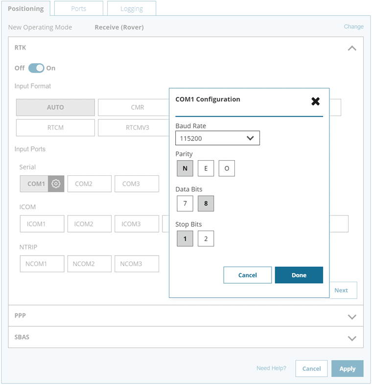
Click on the COM1 configuration and select the Baud Rate value of 115200.
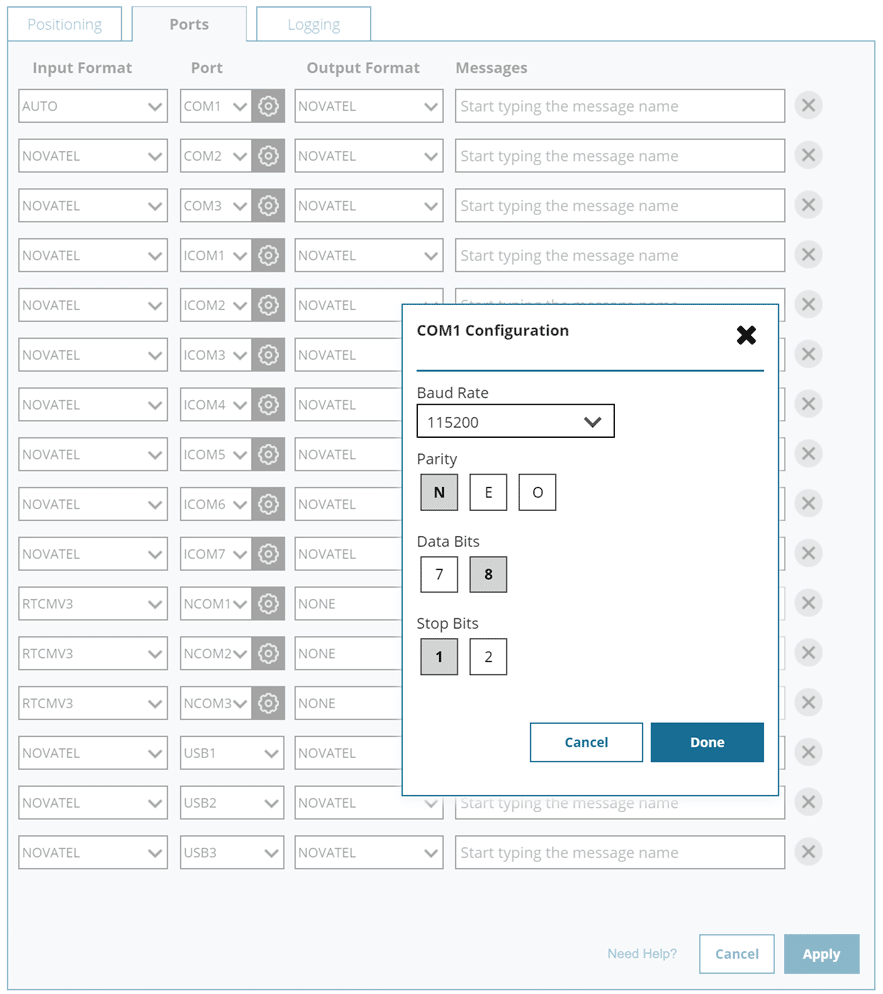
It is also possible to configure Novatel’s NMEA messages to be able to observe them in the Skydel Receiver window.
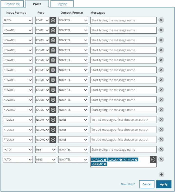
To do this, go to the Ports section of the application and add the following messages on one of the USB virtual ports:
- GPGGA
- GPGSA
- GPGSV
- GPRMC
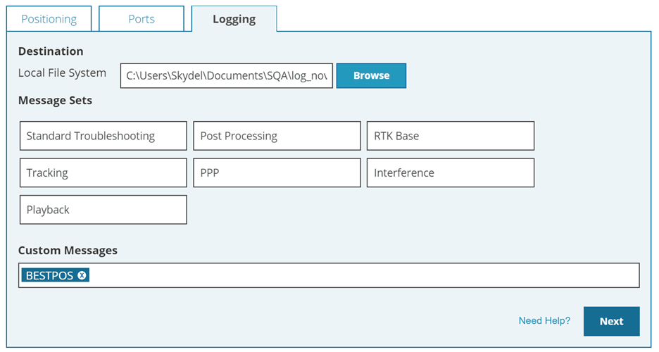
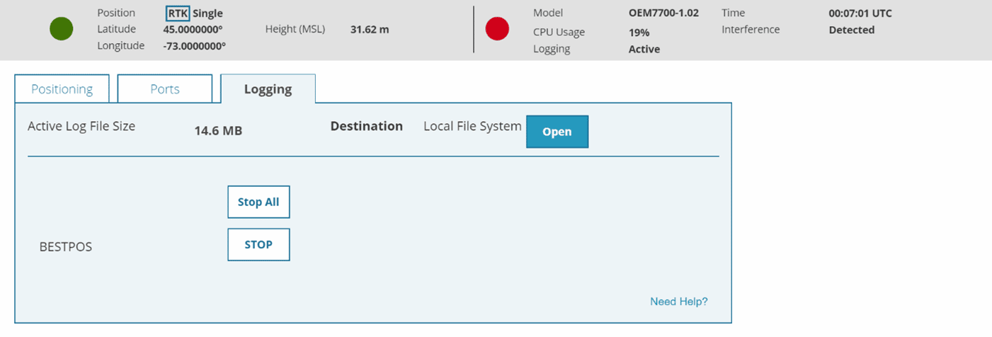
Go to the Logging menu, enter BESTPOS in the Custom messages section, and click Next.
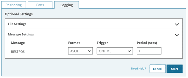
In the logging popup window, select Edit. Change the format of the BESTPOS message to ASCII to save the raw data of the Novatel receiver in text format. Click the Start button.
Then, enter reset in the menu Tools -> Terminal.
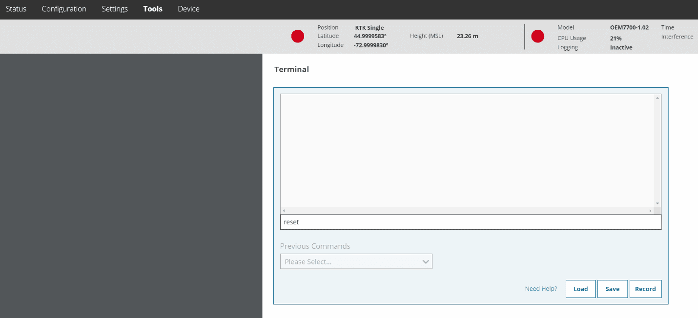
Press enter.
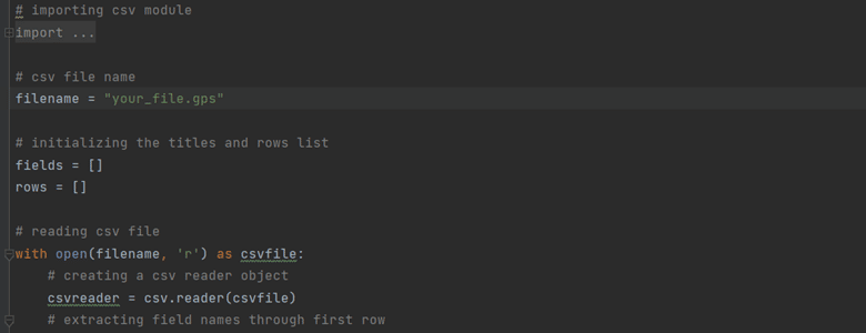
To analyze the accuracy of the simulation, you can look at the data captured in the log file. In this example, we will create a plot of the altitude logged by the receiver over time.
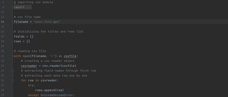
Use the python script main_rtcm.py on the GitHub repo to plot the altitude.
You can access the script here from the Orolia Skydel GitHub
Make sure you have a python from version 3.8 or download the latest python version from https://www.python.org/downloads/.
Put the path of your file in the python script and run the script.
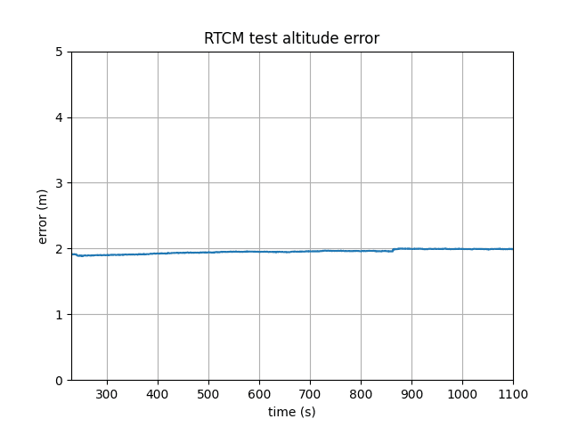
The result obtained in this case study is the following:
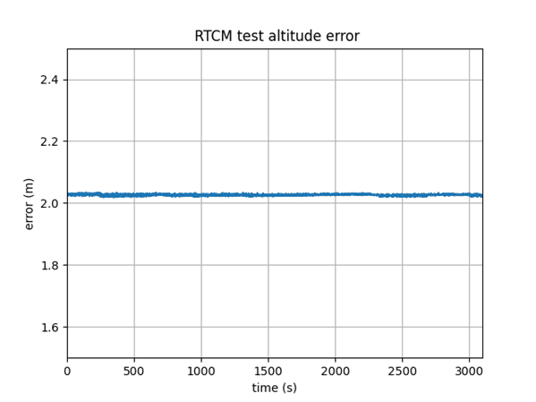
The altitude defined for this test is 2 m. The plot shows an error of less than 3 cm.
In comparison, we get the result if we remove the RTCM plugin from the Base station configuration in Settings -> Plug-ins -> RTCM plugin -> Remove.
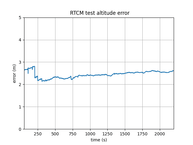
We can see by comparing figures 1 and 2 the stability and the correction provided by the RTCM plug-in.
1.3. Running and Analyzing the Simulation
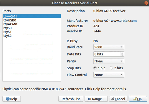
1.3.1 Connecting a Ublox receiver
Even if we use the Novatel receiver for our simulation to have a better precision at the position level, it is also possible to use a Ublox receiver.
To connect the Ublox receiver to the GSG-8, go to the menu Receiver and start by clicking the Connect button and choosing your receiver from the list of available ports.
1.3.2 Running the Simulation
We then start the simulation by clicking on the start button in the Skydel Base Station window.
After a few minutes, the positioning menu turns green. This means that the receiver is working well in RTK mode. Let the Skydel simulation runs for about 30 minutes.
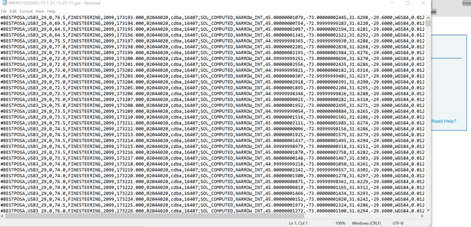
Return to the Configuration menu in the NovAtel Setup and Monitor software at the end of the simulation. Select the Logging tab and click on the button “open” to open the file in the text editor of your choice. Save your data file.
1.3.3 Analyzing the Simulation
If a Ublox receiver is connected to the GSG-8, an initial very simplified analysis would be to use Skydel’s Deviation window to see the result of the error in position without the pseudorange error.
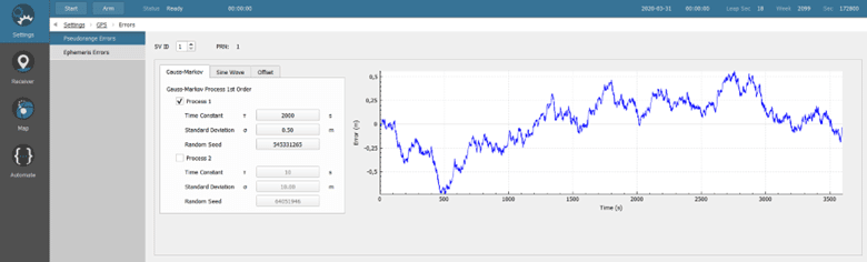
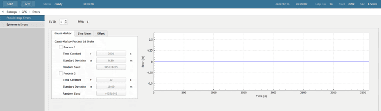
It is also possible to add a pseudo-range error to observe the disturbance on the receiver and see how the receiver will react. To do this, stop the simulation and go to Settings -> GPS -> Pseudorange Errors.
Apply a value of Time constant = 2000 (s) and a Standard deviation = 0.5 (m) both for the Rover and the Base Station.
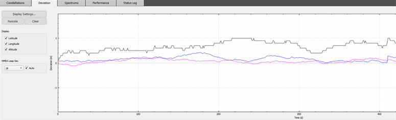
Start Skydel and go to the Deviation tab:
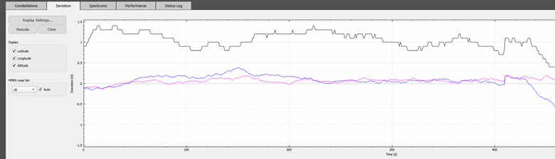
We can see that the error caused a disturbance on the receiver because we see deviation values greater than 1 m.
We then connect the Ublox receiver to the U-center application, and we observe the altitude the variation of the altitude in 4 cases:
- RTCM Plug-In disable, and Pseudo-range error disable.
- RTCM Plug-in disable, and Pseudo-range error enable.
- RTCM Plug-in enable, and Pseudo-range error disable.
- RTCM Plug-in enable, and Pseudo-range error enable.
To know how to connect the Ublox to the U-center on a windows computer, please see “Appendix A” in the User Manual, Skydel RTCM Plug-In User Manual – Orolia.
1. RTCM Plug-in disable and Pseudo-range error disable:
First, to disable the Pseudo-range errors both for the Rover and the base station, go to Settings -> GPS -> Errors and disable the process 1.
Then, make sure the Plugin is disabled in the base station configuration in Settings -> Plug-ins -> Plug-in
1: Start Skydel and the U-center UI.
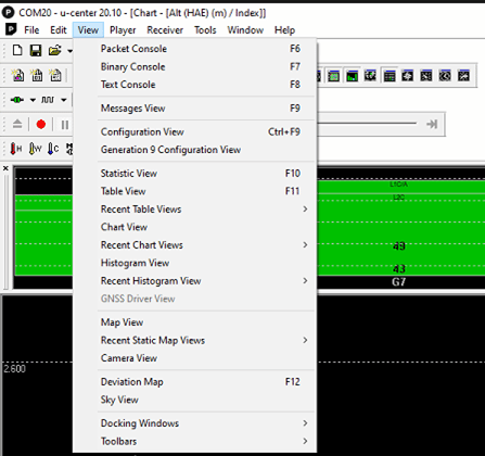
Go to View -> Chart View to show the plot of the altitude.
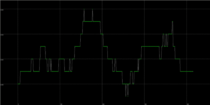
After about 5 minutes of simulation, you can already see the position variation curve received by the Ublox on the chart view.
2. RTCM Plug-in disable and Pseudo-range error enable:
Stop the simulation and allow the Pseudo-range error for both the rover and the base station.
Then start Skydel again.
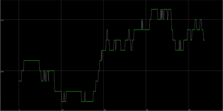
We see the same type of trend for this new example of an unsteady curve. Indeed, the altitude that we have set for this simulation is 2 m. But we see that the position does not stabilize around these 2 m altitude, but it increases until it reaches 3 meters.
3. RTCM Plug-in enables, Pseudorange to disable:
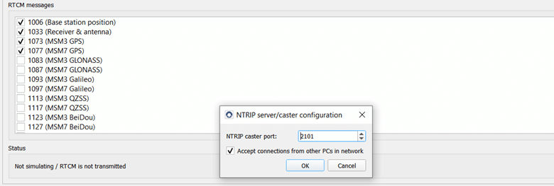
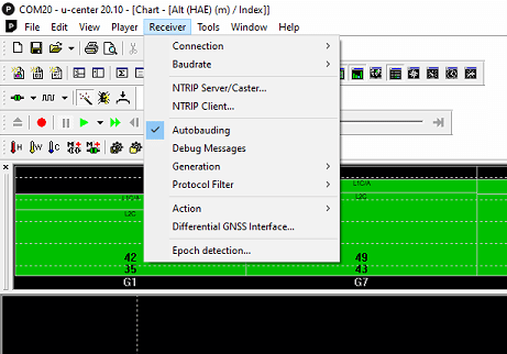
As a reminder, to enable the Plug-in for a Ublox Receiver:
Then click on Configure and check the NTRIP caster port:
Go to U-Center and click on NTRIP client:
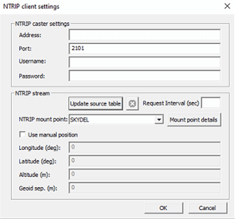
In this window, click on the Update source table.
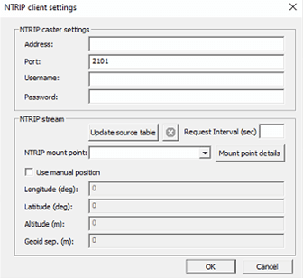
Wait for the Skydel label to appear in the NTRIP mount point, and then click OK to close the window.

After selecting View>Chart View, you can verify that the position variation for the Alt (HAE) has now stabilized to less than 2-3 cm. If you are still not viewing the 3cm or less then there may be an additional step or two needed to enable this in the receiver.
First, from the Receiver tab select ‘Debug Messages’ or alternatively select the bug icon. This will enable all debug messages in the receiver.

If this has not resolved the position deviation then open View>Messages View and open the UBX>CFG>NMEA and in the dialog box ensure that under the Mode Flags you have ‘High Precision Mode’ checked.

4. RTCM Plug-in enable and Pseudo-range error enable
We notice that the Plugin manages to correct the added pseudorange error, and the values obtained are approximately those that we had without the error.

We notice this time that the altitude is stable, even when we add the Pseudorange error.
The error interval is +-0.03m.
2. RTCM Use Case: Using Two GPS Receivers
2.1. Hardware Setup
Two instances of the Skydel application are required to simulate GNSS constellations for both the base station and the rover.
We will show a simple scenario of configuring an RTCM simulation without the RTCM plug-in for this study case.
Here is the hardware configuration used for this case study.
2.2. Software setup
2.2.1. Add a Radio
NOTE: This step is only necessary to add additional radios; a first radio will be preconfigured on your default configuration. Multiple setup options are possible; refer to the main Skydel manual for more information.
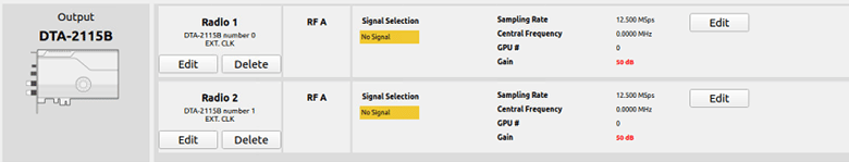
To add a radio, navigate to Settings – Output.

Select the DTA-2115B in the dropdown list and click the Add button twice.
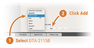
The DTA-2115B will be added with a default device number 0 and default clock settings. If the default values are incorrect for your hardware setup, click Edit to make the necessary changes and click OK when done.
2.2.2. Base configuration
Open a Skydel instance and start a new configuration.
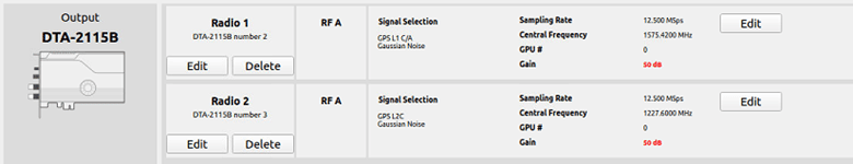
1. Signal selection
Click the Edit button for the RF-A output of Radio 1 and select GPS L1 C/A and GPS L2 for Radio 2.
2. Time synchronization with the base station
Allow the rover simulator to be synchronized with base station simulator. Go to Settings -> Global -> Synchronize simulators. Set checkbox “Sync time (master).”
This will allow the base station simulation to start together with the rover simulation. Click checkbox “Automatically broadcast configuration on simulation start.”
3. Vehicle trajectory
Select base trajectory in Settings->Vehicle->Trajectory.
Remember that the positioning precision depends on the distance between the rover and the base station. The position chosen for the vase is fixed with the following coordinates:
Latitude: 45.0 °
Longitude: -73.0 °
Altitude: 2 (m)

Save your configuration.
2.2.3. Rover station configuration
In this part, you can use the same Rover configuration as described in section 1.2.3.
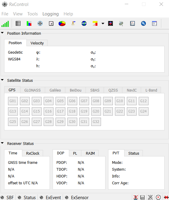
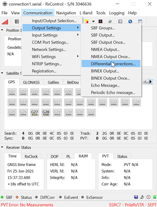
2.2.4. RX Control
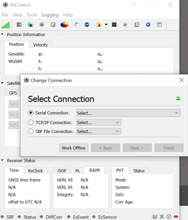
Open your RX control application. You will then see this window:
Then go to the File tab and select change connection.
Then select your serial port according to your configuration.
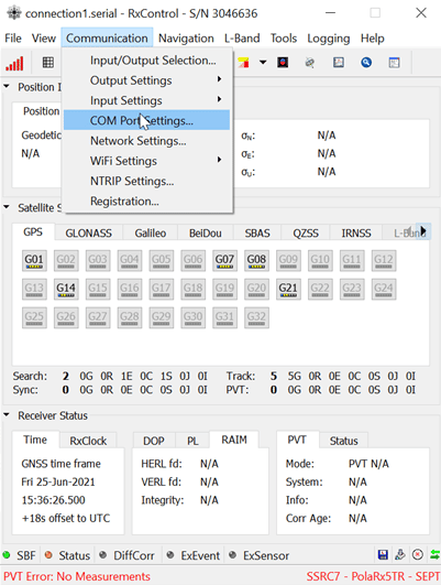
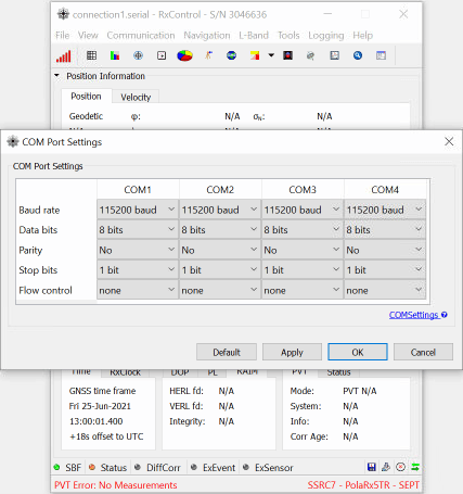
Then go to the communication tab and select COM Port Settings.
Then enter a value of 115200 for the baud rate.
Then go to the communication tab and select Input/Output selection.
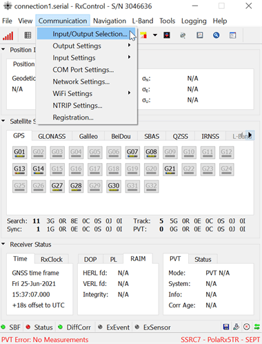
Then, in the COM1 column, select RTCMv3.
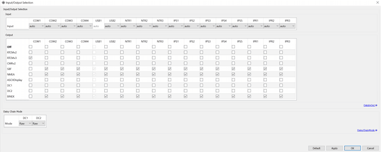
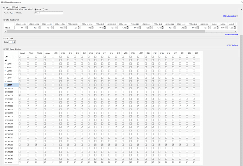
In the same communication tab, select Output settings and go to Differential Corrections:
Now select the following messages in the column of Port COM1:
- MSM3
- MSM7
- RTCM 003
- RTCM 006
2.2.5. NOVATEL CONNECT
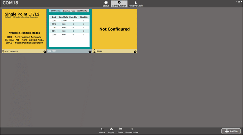
Go to the configuration menu and go to PORT configuration.

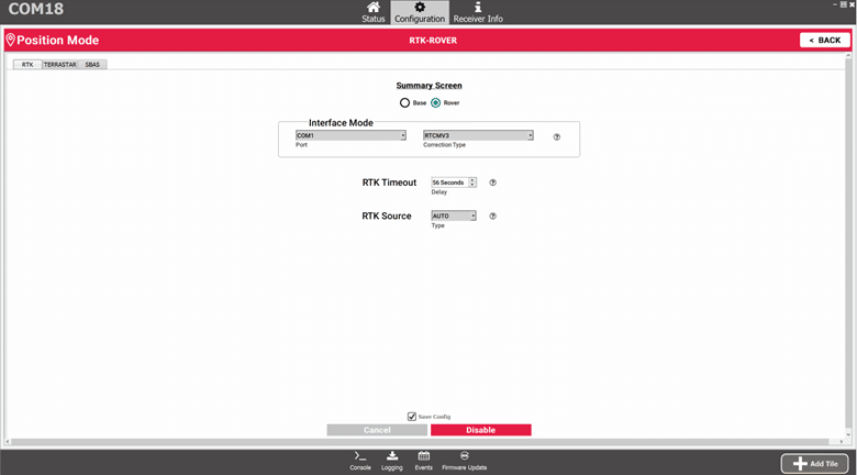
Then return to the menu, go to the window, and click on the Position mode configuration.
Check Rover and in interface mode, select COM 1 and select RTCMV3.
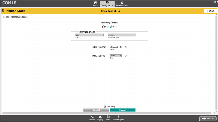
Click on submit to close the window.
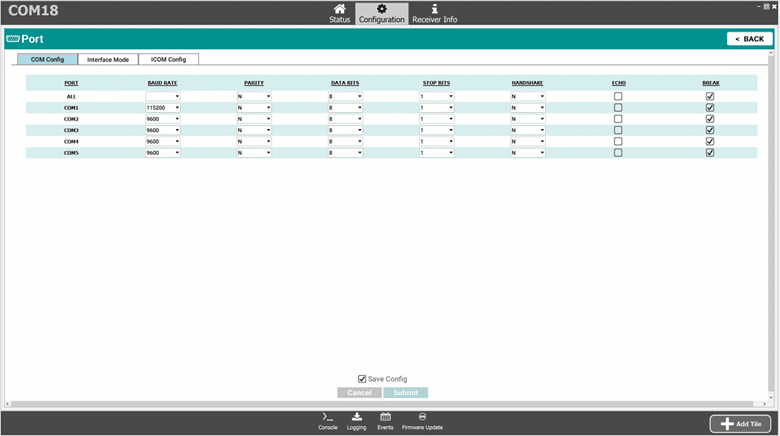
Then return to the main configuration menu and click on the PORT settings.
Then return to the main configuration menu and click on the PORT parameter.
In the COM Config tab, enter a value of 115200 for the baud rate of the COM1 port.
Then go to the next tab and select RTCMV3 in the Receive column of the COM1 port.
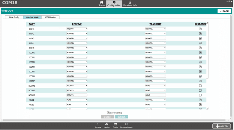
Click on submit to close the window.
Start your Skydel simulation.
Save your configuration and run your python script.
Here is the error figure in the position obtained.
The position of the altitude obtained remains relatively stable at around 2m.
Conclusion
Two different methods to simulate RTCM usage, one based on the RTCM plugin and the other on the multi-instance, simulating two synchronized RF signals.
The plugin method is helpful for users who do not have a base receiver and want to emulate RTCM corrections. The second setup is suitable for those who wish to include the base receiver in the loop.
All this is possible thanks to Skydel’s flexibility and expandability.