Measuring a GNSS Signal and Gaussian Noise Power
Tutorial
INTRODUCTION
This tutorial explains how to measure the output signal power of the GSG-7 or GSG-8 GNSS Simulator. Additionally, it shows how to properly configure Skydel for this type of measurement. Finally, this tutorial also describes how to set up RF equipment to accurately measure the RF power of signals using a spectrum analyzer.
WHAT IS C/N0?
A GPS receiver can measure pseudoranges to a satellite with a precision of 0.5 meters or better. One factor of the GPS signal-ranging accuracy is the carrier-to-noise ratio, C/N0. C/N0 (“Carrier power divided by noise Power density” or “Carrier to Noise Density ratio”) is the ratio of the received signal power, to the spectral density power of the noise. The C/N0 is expressed in units of dB-Hz.
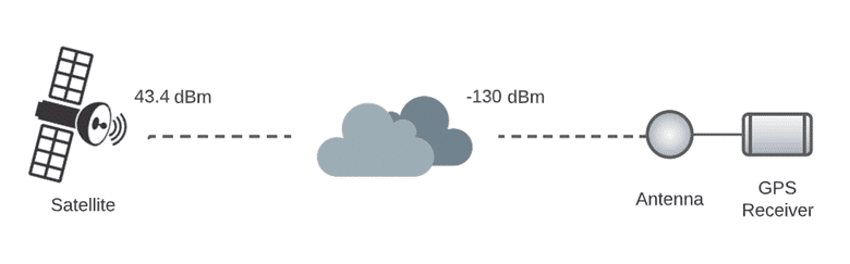
When the GPS signal is received, the signal is typically swamped by noise at the receiver’s input. Following the ICD standard documentation, the minimum level of the GPS L1 CA signal that reaches the earth’s surface must not fall below -160dBW (-130dBm). To maintain this signal level, the transmitter power of the GPS L1 CA is approximately 25W (~14 dBW). The satellite’s altitude is approximately 20,200 kilometers, so the spreading loss will be applicable. The corresponding path loss is around -157.1 dB.
Noise sources – like thermal noise – generate power in proportion to the bandwidth of a system and a temperature. Thermal noise is generally calculated at 290°K. The noise power spectral density for noise is: N0=kT (W/Hz). where, k is Boltzmann’s constant (1.3803 × 10⁻²³ J/K), and T is the absolute temperature(K).
N0=1.3803 × 10-23×290=-204 dBW⁄Hz= -174 dBm/Hz
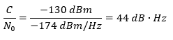
Thus, the spectral power density of the thermal background noise being about –174 dBm/Hz (at a temperature of 290°K), the typical Carrier to Noise Density ratio (C/N0) of GPS L1 C/A is then:
HOW THE C/N0 WORKS IN SKYDEL
It is possible to reproduce actual GNSS signal conditions using Skydel and the GSG-7/8’s SDR radio:
The “reference power” for all GNSS signals generated by Skydel is around -130dBm (See this in the “Constellations” Tab).
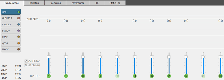
A slider set to “0 dB” will force the signal to be at -130dBm.
When Gaussian Noise is activated, Skydel generates noise such that the C/N0 ratio between a simulated GNSS signal at -130dBm and the noise will be 44 dB.Hz
If the user increases the satellite power (ex: using the sliders) by 1dB, the C/N0 ratio will be increased by 1dB.
However, there are some caveats:
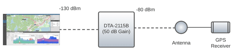
- Skydel transmits GNSS signals at a higher power to simulate an antenna amplifier. Depending on the receiver’s design, this might change the resulting C/N0 reported by the receiver.
- When transmitting the signal of multiple satellites simultaneously, the signal of other satellites is perceived as noise. This also affects the C/N0 reported by a receiver.
To precisely verify the C/N0 ratio of the signal generated by Skydel, we use a Spectrum Analyzer to measure the power of a single satellite and then the power of the Noise alone, without any GNSS signals.
HARDWARE SET-UP
The GSG-7 or GSG-8 hardware models that can be used to run this simulation are:
| GSG-811 | GSG-821 | GSG-831 | GSG-842 |
| 1 RF Output 1 GPU/1SDR | 2 RF Outputs 1 GPU/2 SDR | 3 RF Outputs 1 GPU/3 SDR | 4 RF Outputs 2 GPU/4 SDR Same configuration as BroadSim |
| GSG-711 | GSG-721 | GSG-731 |
| 1 RF Output 1 GPU/1 SDR | 1 RF Output 1 GPU/2SDR | 1 RF Output 1 GPU/3 SDR |
But, users can use any type of SDR radio compatible with Skydel. See the user manual for more information.
*Can be also used with a GSG-7
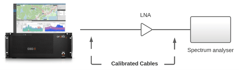
The RF equipment used with the GSG-8* for RF measurements is the following:
- Tektronix Spectrum Analyzer RSA-5103B
- Calibrated SMA male RF cable
- GSG-8* GNSS simulator
- External LNA (Low Noise amplifier)
The Low Noise Amplifier (LNA) is a radio frequency (RF) component used in the Global Navigation Satellite System (GNSS) front-end receiver to amplify the RF signals received by the antenna to the desired level. The GNSS LNA increases the desired signal strength by adding minimal noise and distortion to mitigate the impact of noise added by subsequent components in the RF receiver chain, thereby improving the signal-to-noise ratio (SNR) and overall system performance.
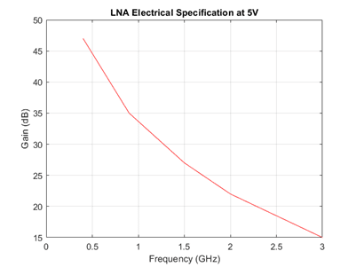
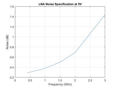
The LNA model that we use is the ZKL-33ULN-S+, 400 – 3000 MHz, 50Ω.
Based on the LNA electrical specifications, we estimate the overall LNA amplification gain for the GPS L1 CA band (1575.42 MHz) to be around 25.72 dB.
The table below shows the attenuation power of the RF cables and the amplification power of the LNA at the GPS L1 band frequency of 1575.42 MHz:

SKYDEL CONFIGURATION
To launch Skydel on the GSG-7/8, type Skydel-SDX in the terminal. In Windows, locate Orolia’s Skydel in the start menu, and click it.
Click “Continue” and then select “New Configuration.”
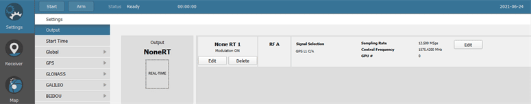
Add an output
To launch Skydel on a Linux system, type Skydel-SDX in the terminal. In Windows, locate Orolia’s Skydel in the start menu and click it.
Click “Continue” and then select “New Configuration.”
Add signals
Click “Edit” in the Radio setting to set the radio configuration. Then, click on “Signal Selection – Edit” to select the signal.
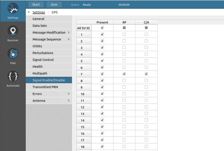
Go to GPS -> Signal Enable/Disable – keep only one visible satellite as shown below:
Set vehicle position
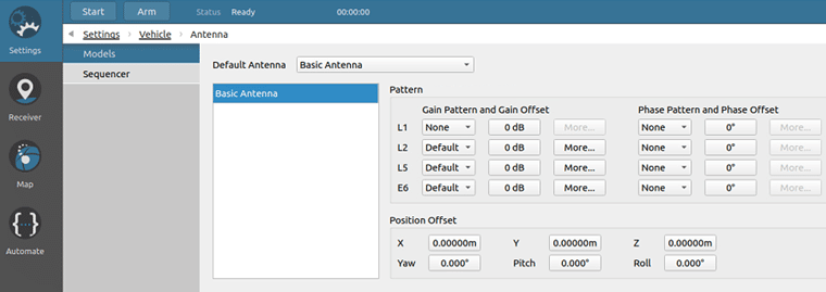
We used the default fixed position set by Skydel, but the vehicle antenna settings can be changed. To do this, go to Settings –> Vehicle -> Antenna and set the Gain Pattern and Gain Offset L1 parameters to None.
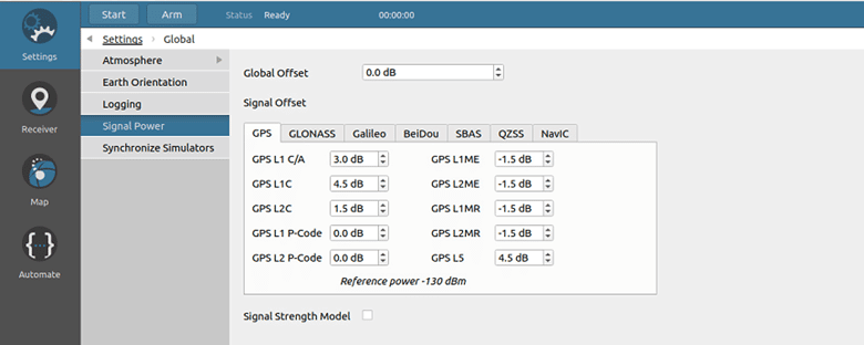
Set global parameters
Go to Global -> Signal Level and disable Signal Strength Model.
MEASURING GNSS POWER LEVEL
Please follow the instructions below to measure your RF signal and noise power within Skydel:
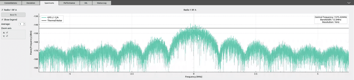
- Start Skydel
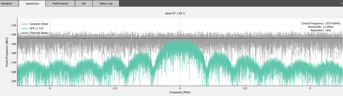
- Check the Spectrum tab in Skydel: the expected max power level should be -140dBm.
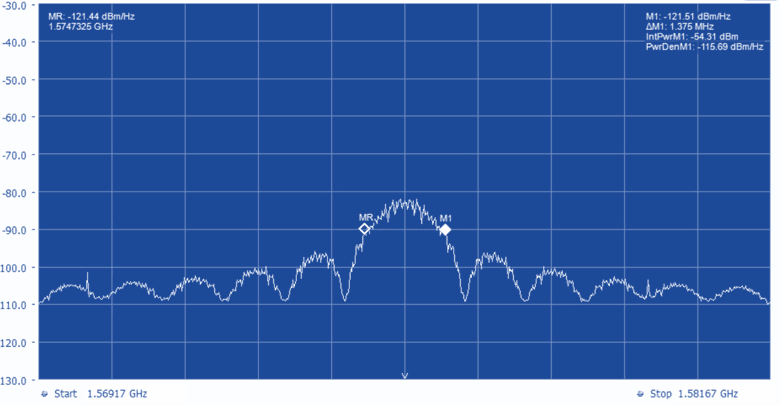
- Set the Spectrum analyzer for power measurements.
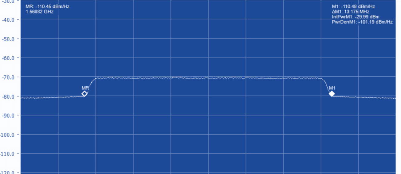
- Report the power level centered on the GPS L1 CA signal:
For better accuracy, perform the measurements for the enabled GNSS signal. Other satellites should remain unchecked on the Signal Enable/Disable tab. Stop the simulation. Enable the Gaussian noise on the Signal selection tab. Also, disable the satellite that was activated and set the Spectrum analyzer for the power of the noise only. 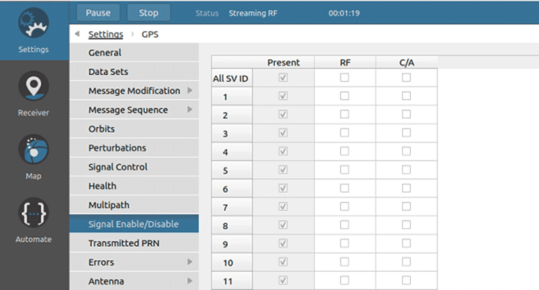
We evaluate the gain of the LNA added to the attenuation of the RF cables to an approximate value of 22.8 dB.
The results obtained for signal strength and noise are shown in the table below:

CONCLUSION
Skydel’s powerful software-defined architecture allows for a great deal of flexibility. Regardless of the hardware platform, Skydel provides users with not only a multitude of configuration possibilities, but built-in measurement and performance tools as well.
In this tutorial, we have shown how to use Skydel to measure a GNSS signal and Gaussian noise power.
Skydel generates a base band GNSS signal at -130dBm. When Gaussian Noise is activated, Skydel generates noise such as the ratio between a simulated GNSS signal at -130dBm and the thermal background noise of C/N0 = 44 dB-Hz.
When generating RF signals with Skydel connected to an SDR radio, the measured signal strength will depend on your Skydel configuration settings, the radio gain, and the losses of RF equipment. Thus, determining the actual value of your CN0 will help you determine what the CN0 is at the output of your GNSS system.