Creating Custom Signals
Technical & Application Notes
This document describes how – using Skydel’s Custom Signals feature – users can create a customer GNSS signal.
This feature allows users to create their own custom signals and attach them to GNSS satellites so they are streamed along regular GNSS signals. The purpose of this feature is to provide a tool to advanced users who want to design GNSS or non-GNSS (such as LEO constellation) signals and evaluate their performance. This feature lets users avoid the arduous task of designing an engine that will simulate the dynamics of satellites, vehicles, and all of the associated environmental effects (atmospheric, multipath, jamming, spoofing). Thus, users can focus all their efforts on the design and architecture of the signal itself.
1. Architecture
For existing GNSS signal generation, Skydel already knows all the signals specifications and how to generate the navigation message bits as well as the code chips. However, in order to develop a custom signal, users must provide information and compiled code to Skydel.

The diagram above shows that the user needs to provide an XML file and a C++ shared library (.dll in Windows or .so in Linux) for each custom signal. Nevertheless, the same library can be shared by several custom signals.
As for the legacy signals, the Skydel engine automatically simulates the satellite visibility, signal dynamics, and impairments (atmospheric delays, multipath). The custom signal user must provide the signal data in the correct timeframe scheduled by the Skydel Engine.
A custom signal is composed of an arbitrary number of Subcarriers and Codes. The signal composition is described in an XML file. The code chips must be provided through a C++ shared library, as illustrated in the figure below.

The IQ samples are generated according to the following equation:

where:
- A a constant (in ℂ) multiplication factor
- C the number of codes
- Ci (t) is the code chips value (-1 or 1) defined in the shared library (DLL)
- SC(t) the subcarriers defined as:

where:
- S is the number of subcarriers
- SCj (t) is the subcarrier Real values defined in the XML file
With this approach, it is possible to generate several GNSS modulation types, such as BPSK(N), BOC(M,N) and MBOC (M,N,P). Some examples of legacy GNSS signals are provided in Annex A. Tracking and accuracy of these signals have been validated on a GNSS receiver.
An eventual evolution of the custom signal will bring even more genericity to this feature. The objective is to have the possibility to generate (at minimum) all the legacy signals using the custom signal feature. A description of these possible evolutions is given in Annex B.
1.1. XML file

CustomSignal
Version: Document interface version; current version is “1.0”.
NavMsg: Optional Boolean. If missing, it will try to get a navigation message from the shared library. If set to True, it will generate an error if the navigation message is missing from the shared library.
Constellation: The satellite constellation to which this custom signal will be attached.
CentralFreq: Custom signal’s central frequency, in Hertz.
Bandwidth: Custom signal’s bandwidth, in Hertz.
DLLPath: Path to the shared library relative to the XML.
SignalLevel: Default power offset to the constellation reference, in dB.
Subcarrier
Id: Subcarrier identifier.
Rate: Subcarrier rate, in Hertz.
Coef: An array of real numbers representing the subcarrier chip values. For example, a BOC would have the [-1, 1] coefficients. A CosBOC at half power would have the [-0.5, 0.5, 0.5, -0.5] coefficients.
Code
Id: Code identifier. It can be used to distinguish different custom signals in the same shared library.
ModulationCoef
Real: The real part of the multiplier is applied to every sample.
Imag: The imaginary part of the multiplier is applied to every sample.
1.2. Shared library

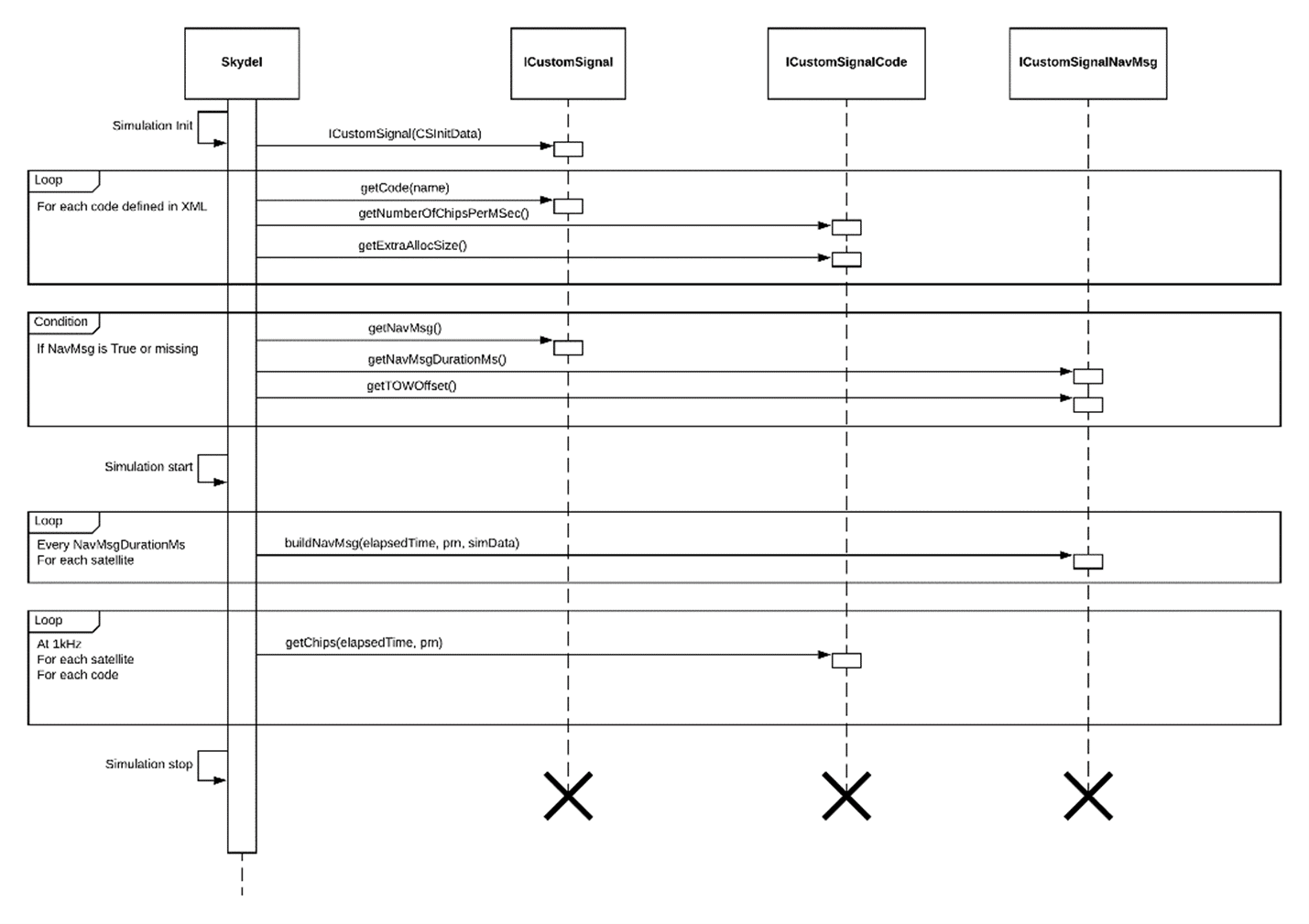
ICustomSignal
Constructor: Your User’s implementation constructor must take a reference to a constant CSInitData structure containing various simulation start information.
getNavMsg: Returns a pointer to the navigation message object or nullptr if this shared library does not define any.
getCode: Returns a pointer to the code object that matches the null-terminated identifier name or nullptr if this is not a recognized name.
ICustomSignalCode
getNumberOfChipsPerMSec: Returns the code rate in chips per millisecond.
getChips: Copy custom chips for elapsed time elapsed and PRN prn into the buffer chips. The buffer is guaranteed to be getNumberOfChipsPerMSec() + getExtraAllocSize() long.
getExtraAllocSize: Extra bytes to allocate for the chips buffer.
ICustomSignalNavMsg
getNavMsgDurationMs: Returns the navigation message duration in milliseconds.
buildNavMsg: Called every getNavMsgDurationMs() with updated simulation data.
getTOWOffset: Returns the navigation message’s offset to the constellation’s Time Ofof Week.
2. Implement a custom signal
To implement a custom signal, users need to develop a C++ shared library (.dll on Windows, .so on Linux). Any modern C++ IDE should be compatible. Everything needed to implement is defined in the header file custom_signal_interface.h.
All elapsed time arguments are in milliseconds relative to the simulation start time. All PRN arguments are the legacy signal PRN number.
2.1. Implement ICustomSignal
Ideally, users should implemented ICustomSignal for their your shared library to be usable by Skydel. This class is instantiated at every simulation start and destroyed at every simulation stop. In the implementation .cpp file, users must add the following line and replace MyCustomSignal with their class name:
DEFINE_CUSTOM_SIGNAL(MyCustomSignal)
2.2. Implement ICustomSignalCode
The key function of that class is getChips. It is called every millisecond for every visible satellite. The implementation must copy the code chips potentially multiplied by a navigation message bit. The chips must be the ones at transmission time; Skydel will handle the propagation delay. The chips are uint8 values of either 1 or –1; anything else leads to undefined behavior. The chips buffer is guaranteed to be getNumberOfChipsPerMSec() + getExtraAllocSize() long but only the getNumberOfChipsPerMSec() will be used for the simulation. getExtraAllocSize() is useful if users need some padding to optimize their chips generation algorithm.
2.3. Implement ICustomSignalNavMsg
The navigation message implementation will not return anything directly to Skydel (the navigation message is modulated with the ranging code inside the DLL). It is a facility to receive simulation data (such as satellite’s ephemerides, ionospheric, UTC, and polar motion terms) and set some internal states accordingly. The buildNavMsg function is called every getNavMsgDurationMs() milliseconds, aligned to the constellation’s time of the week. Users can offset this message by returning something other than 0 in getTOWOffset().
3. Using a custom signal
3.1. Import a custom signal
Once users have prepared their xml file and compiled their shared library, they are ready to use the custom signal inside Skydel.
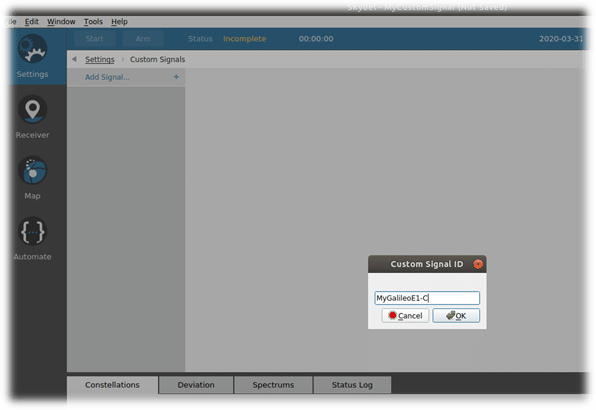
The first thing to do is to add the Custom Signal to the scenario. To do so, under the Custom Signals settings, click on Add Signal… Give it a useful name and browse for the signal’s XML file.
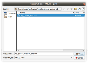
IMPORTANT: Ensure that the shared library is located as specified by the XML file.
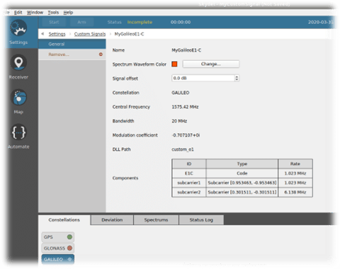
Users should see a summary of their custom signal definition below. They can change the power offset of their custom signal compared to the reference level of the constellation of their signal. Note: The reference level of each constellation is shown on the settings page “Settings –> Global –> Signal Level.”
3.2. Add the custom signal to the simulation
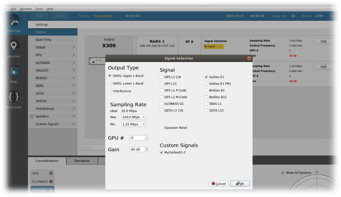
Now that the signal is known, it can be added to a GNSS output. To do so, go to the “Settings –> Output” page, and click on “Edit” of one of the available outputs.
NOTE: to add a Custom Signal to an output:
- A signal of the same constellation must first be added to the same output (Galileo E1 in this example)
- The bandwidth of the output must cover the custom signal.
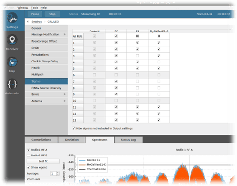
Users can control the signal transmission per satellite by going on the Signals tab under the attached constellation. Users can either enable/disable the original and custom signals transmitted by each satellite.
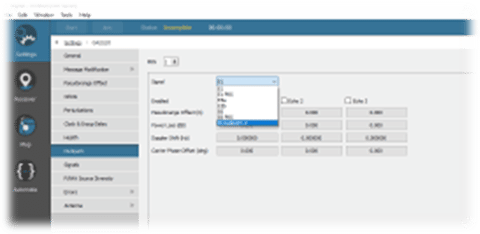
It is also possible to apply multipath on the custom signals in the usual multipath interface. The created custom signals are automatically added to the list:
3.3. Start the simulation
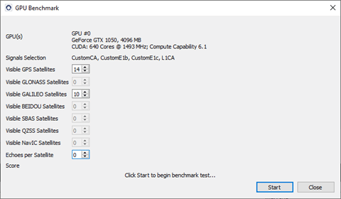
Before starting a simulation, the simulator’s performance can be tested with the custom signals, as is done for the legacy signals. A score higher than 1.1 confirms that a simulation can be started with the current configuration.
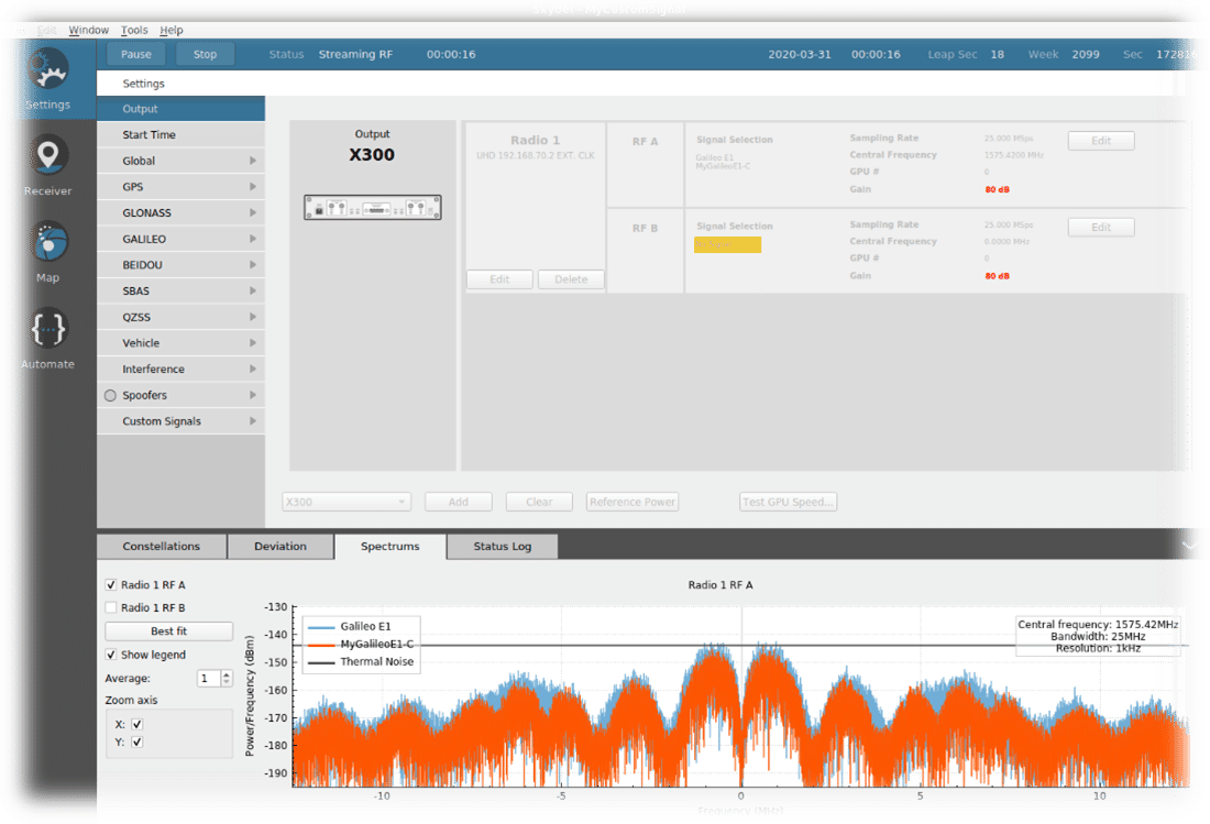
Then, users can start a simulation using their custom signal. They will be able to see the spectrum of their custom signal like this:
Annex A -Custom signal examples
GPS C/A
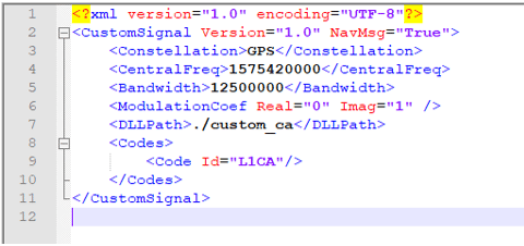
The external library source code example is available on request.
Galileo E1
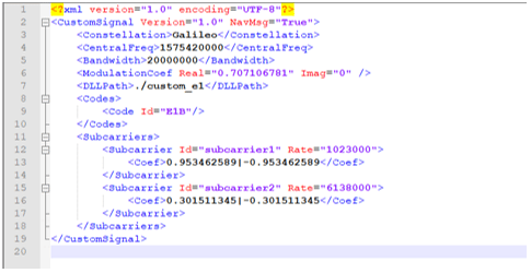
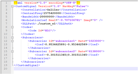
With the current version of Custom Signal, Galileo E1 is generated with 2 customs signals, one for each component. The 2 components are automatically added during the modulation in the Skydel engine.
Galileo E1b
Galileo E1c
The external library source code example is available on request.
Annex B -Future Evolutions
The custom signal is an innovative and experimental feature, and evolutions will be planned in function of customer feedback.
There are plans to update the features in order to reach our objective of simulating all the legacy signals.
FDMA Signals
The current version of this feature does not manage FDMA signals such as GLONASS G1 and G2. These signals use a different central frequency for each satellite vehicle (instead of using a different ranging code). We need to manage this feature in the XML definition file and the shared library.
All Constellations
Currently, Custom Signals works with GPS, Galileo and BeiDou. Our objective is to support all the other GNSS constellations: GLONASS, QZSS, NAVIC and SBAS.
Complex Signals
In the current version of the custom signal feature, many different signals can be generated, but we want to continue to improve the genericity of the feature for two reasons:
- With the current custom signal architecture and modulation equation, some signals like Galileo E1 must be generated with two custom signal components. We want to have a way to describe modulation functions that can define complex signals such as Galileo E1 or even E5 with only one custom signal component.
- Some legacy signals like GPS L1C (TMBOC(6,1,1/11)) cannot be modulated with the current modulation function. We need a more generic way to describe this function.
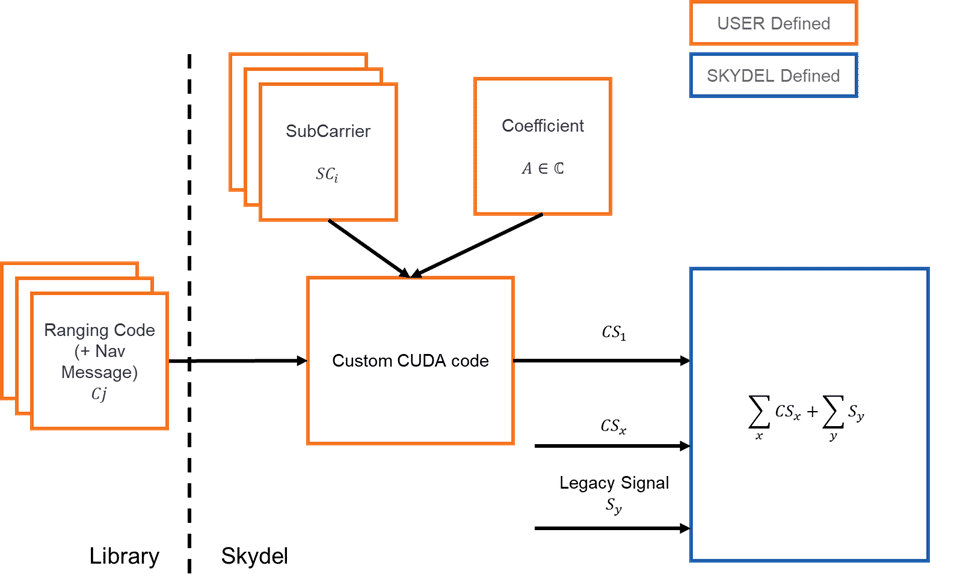
The proposed method we are investigating is to let the user describe this function by directly writing the script that will perform the operation. We will provide the user a way to write the code executed by the graphic card to process all the components of the custom signal. This is possible thanks to a function of the CUDA programming language (used by NVIDIA graphic cards).
In that way, users will be completely free to modulate the collection of subcarriers and codes in the way they want.
The architecture will look as follows:
Conclusion:
Skydel is a powerful tool for simulating almost any satellite communication scenario. In this document, we presented a method to create a custom signal using code chips provided by a C++ shared library. We began by first showing how to implement your own custom signal and then how to use it. Several evolutions of this feature are to come.
