Front panel
.png)
Front Panel of the WR-ZEN TP Legend
| # | Name | Information | Ref. |
|---|---|---|---|
| #1 | 2x Management Ethernet (RJ45) | ● 10/100/1000 ethernet network interface (eth0 & eth1) | WR-ZEN TP |
| #2 | FMC expansion port | ● Slot placed to allow the use of FMC cards | WR-ZEN TP |
| #3 | 2x SFP Fiber Ports | ● 1GBps SFP compatible | |
| #4 | 1x ARM Mini-USB (B) UART | ● Serial UART Mini-USB (B) | White RabbitIEEE 1588-2008 (PTPv2) |
| Timing output | |||
| #5 | 10 MHz output |
● SMA connector (F) |
Virtual Clock Overview |
| #6 | CLK TTL output |
● SMA connector (F) |
Virtual Clock Overview |
| #7 | PPS output |
● SMA connector (F) |
Virtual Clock Overview |
| Timing input | |||
| #8 | PPS input |
● SMA connector (F) |
External Reference (GM) |
| #9 | 10 MHz input |
● SMA connector (F) |
External Reference (GM) |
| #10 | LED |
● Red: error LED |
General Status |
| #11 | DB9 PPx/CLK A |
● High level output: 1.7V +/-0.2V |
|
| #12 | DB9 PPx/CLK B |
● Selectable 50 Ω termination |
|
| #13 | TOD0 |
● RJ45 RS422 |
|
| #14 | TOD1 |
● RJ45 RS422 |
|
| #15 | INFO/CTRL Button | ● Button used to access to information a control settings | |
| #16 | LCD Display | ● Panel for alert & configuration information | LCD screen menu |
| #17 | Power/Reset Alarm button  |
● Power On/Off the device and perform a factory reset | Recovery Mode |
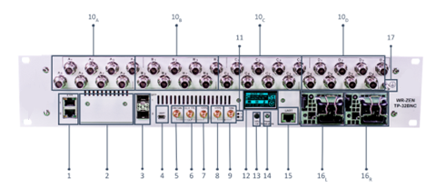
Front Panel of the WR-ZEN TP 32-BNC Legend
| # | Name | Information | Ref. | |||||
|---|---|---|---|---|---|---|---|---|
| #1 | 2x Management Ethernet (RJ45) | ● 10/100/1000 ethernet network interface (eth0 & eth1) | WR-ZEN TP-32BNC | |||||
| #2 | FMC expansion port | ● Slot placed to allow the use of FMC cards | WR-ZEN TP-32BNC | |||||
| #3 | 2x SFP Fiber Ports | ● 1GBps SFP compatible | White RabbitIEEE 1588-2008 (PTPv2) | |||||
| #4 | 1x ARM Mini-USB (B) UART | ● Serial UART Mini-USB (B) | ||||||
| Timing output | ||||||||
| #5 | 10 MHz output |
● SMA connector (F) |
Virtual Clock Overview | |||||
| #6 | CLK TTL output |
● SMA connector (F) |
Virtual Clock Overview | |||||
| #7 | PPS output |
● SMA connector (F) |
Virtual Clock Overview | |||||
| Timing input | ||||||||
| #8 | PPS input |
● SMA connector (F) |
External Reference (GM) | |||||
| #9 | 10 MHz input |
● SMA connector (F) |
External Reference (GM) | |||||
| #10 A | 8x Configurable PPS/10 MHz |
● BNC connector (F) |
||||||
| #10 B | 8x Configurable PPS/10 MHz |
● BNC connector (F) |
||||||
| #10 C | 8x Configurable PPS/10 MHz |
● BNC connector (F) |
||||||
| #10 D | 8x Configurable PPS/10 MHz |
● BNC connector (F) |
||||||
| #11 | LED |
● Red: error LED |
General Status | |||||
| #12 | LCD Display |
● Panel for alert & configuration information |
LCD screen menu | |||||
| #13 | INFO/CTRL Button |
● Button used to access to information a control settings |
||||||
| #14 | Power/Reset Alarm button |
● Power On/Off the device and perform a factory reset |
Recovery Mode | |||||
| #15 | 1x Management UART (RJ45) | Serial UART RS232 on a RJ45 connector with pinout (USB-RJ45/RS232 adaptor not included) |
||||||
|
||||||||
| Power Supply | ||||||||
| #16 L | Power Supply #1 |
● Swappable & monitorable module: |
||||||
| #16 R | Power Supply #2 |
● Swappable & monitorable module: |
||||||
| #17 | Ground | ● Ground connector of the device  |
||||||


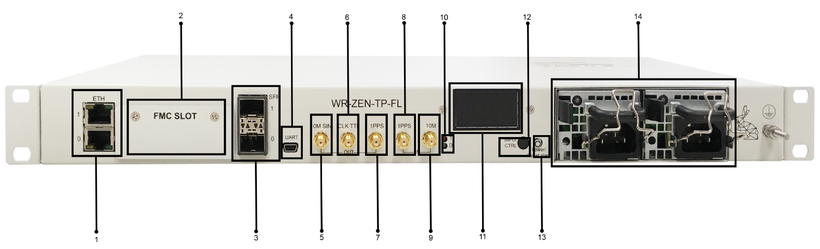
Front Panel of the WR-ZEN TP-FL Legend
| # | Name | Information | Ref. | |||||
|---|---|---|---|---|---|---|---|---|
| #1 | 2x Management Ethernet (RJ45) | ● 10/100/1000 ethernet network interface (eth0 & eth1) | WR-ZEN TP-FL | |||||
| #2 | FMC expansion port | ● Slot placed to allow the use of FMC cards | WR-ZEN TP-FL | |||||
| #3 | 2x SFP Fiber Ports | ● 1GBps SFP compatible | White RabbitIEEE 1588-2008 (PTPv2) | |||||
| #4 | 1x ARM Mini-USB (B) UART | ● Serial UART Mini-USB (B) | ||||||
| Timing output | ||||||||
| #5 | 10 MHz output |
● SMA connector (F) |
Virtual Clock Overview | |||||
| #6 | CLK TTL output |
● SMA connector (F) |
Virtual Clock Overview | |||||
| #7 | PPS output |
● SMA connector (F) |
Virtual Clock Overview | |||||
| Timing input | ||||||||
| #8 | PPS input |
● SMA connector (F) |
External Reference (GM) | |||||
| #9 | 10 MHz input |
● SMA connector (F) |
External Reference (GM) | |||||
| #10 | LED |
● Red: error LED |
General Status | |||||
| #11 | LED |
● Red: error LED |
General Status | |||||
| #12 | LCD Display |
● Panel for alert & configuration information |
LCD screen menu | |||||
| #13 | Power/Reset Alarm button |
● Power On/Off the device and perform a factory reset | Recovery Mode | |||||
| #14 | 1x Management UART (RJ45) | Serial UART RS232 on a RJ45 connector with pinout (USB-RJ45/RS232 adaptor not included) |
||||||
|
||||||||
| Power Supply | ||||||||
| #15 L | Power Supply #1 |
● Swappable & monitorable module: |
||||||
| #15 R | Power Supply #2 |
● Swappable & monitorable module: |
||||||
| #16 | Ground | ● Ground connector of the device |
||||||