Multi-sources & Resiliency
To ensure continued operation over possible failures, the WR-ZEN incorporates an innovative system that handles multiple timing sources. It also synthesizes these timing sources into a simplified state (a.k.a Virtual Clock State) to ease the monitoring of the device and distributes a common timing information to the down layers.
Timing Sources
The WRZ-OS can handle multiple timing sources in order to discipline the local oscillator of the device. These timing sources can be of different types:
- External Reference (Front panel connectors)
- White Rabbit (High-Accuracy PTP)
- NTP (Survey mode only) → Coming soon!
- Holdover (Always used as last timing source if available)
Note: PTP as timing source: A pure PTP timing source (slave) should not be selected if the timing is then re-distributed using WR (master). Indeed, the jittered correction run by PTP clock is not compatible with the precision needed for WR/HA distribution.
Note: NTP Timing source (Survey mode): Due to its poor accuracy, NTP protocol is always in Survey Mode and thus cannot actively discipline the local clock.
Then, a maximum total of 5 timing sources of the same or different types can be handled. FOCA: The Failover Clock Algorithm details the common parameters shared by all the timing sources and how they are used to determine their states.
FOCA: The Failover Clock Algorithm
The FOCA has been designed for the purpose of automatically switching from one timing source to another by applying the following policy:
In case of failure of the active timing source, switch to the next ready timing source.
This algorithm is based on the “Best Master Clock Algorithm (BMCA)” detailed in the PTP IEEE 1588-2019 standard but acts only in case of failure and not when the “best” source appears in the network. It also enforces the evaluation of the timing sources in a rank order configured by the user. FOCA algorithm has been designed to provide a “safer” approach than BMCA or even ABMCA (Alternate BMCA) to handle switching between multi-references. Its main characteristics are:
- Provides a deterministic behavior.
- Does not allow a new (rogue) node to become the active reference.
- Recovers back to normal state must be done under the supervision of an operator.
- Allows switching between cross WR/PTP profiles and multiple external timing sources.
- Has been designed with tree network topology in mind and it is not optimized for ring topology.
The following figure depicts a configuration where the first two timing sources are employing WR protocol, followed by an external GNSS receiver connected to the front panel reference (GM) and finally ending with the holdover to slowly drift until corrective maintenance. It also illustrates how the two strategies of the FOCA algorithm behave.
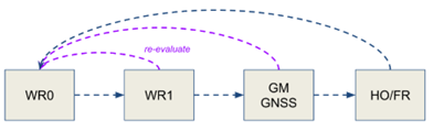
Multi-timing sources handle by FOCA policy with its two strategies: only fall-down (blue) & re-evaluation (purple)
An example of the behavior is given by the scenario illustrated in the next image where the following events are shown:
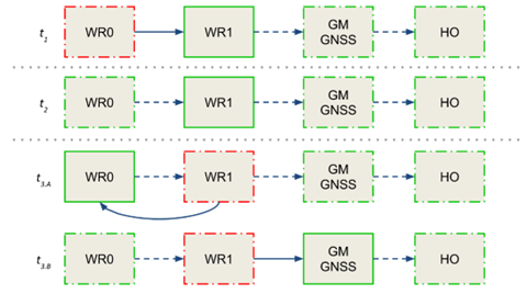
FOCA algorithm under scenario 1
- In t1, the active reference (solid green line) is WR1 because the primary reference has reached a CRITICAL state (dashed red line).
- In t2, the primary reference WR0 becomes available again (dashed green line) but the device keeps using WR1 as the active reference as no failure has been detected on this timing source.
- In t3, an error is detected on WR1 and the FOCA algorithm will act differently according to the configuration of its strategy.
- If the strategy is to re-evaluate all timing sources when a failure occurs, and the primary reference is eligible, the WR0 will be selected as the active reference.
- If the strategy is to only fall-down, the FOCA algorithm will select the next available timing source in the list and will thus lock on the external GNSS reference. With this strategy the only way to use back WR0 as the active reference is to restart the devices’ synchronization daemon (/etc/init.d/ppsi restart) or to reach the last timing source and wait for a critical error.
Another key aspect of FOCA is how to determine when there is a “failure” on a timing source. Some cases are obvious such as the link is down, no packets are exchange but other cases can be more complex to identify: all these cases are detailed in the appendix VCS code tables (Grand Master (GM VCS Code)).
For a deeper understanding of the behavior of the FOCA algorithm it is recommend reading the section Others in the appendix where more scenarios are detailed.
Note: FOCA is based on BMCA, thus it is compatible with all the clock quality and timing information fields. In other words, this means that a device running FOCA strategy can provide timing to a BMCA device and BMCA information is provided to FOCA algorithm.
Virtual Clock Overview
The concept of “Virtual Clock” has been introduced in the new version of WRZ-OS to aid monitoring of the global timing status of the device. It allows to abstract the way the timing sources discipline the local oscillator and summarizes how the device will announce its own clock information through the outputs.

Data-flow between timing sources, virtual clock and outputs
When using the FOCA policy (see Data-flow between timing sources, virtual clock and outputs), the virtual clock will be fed by the active timing source (e.g., tsrc1), then this information (clock quality & time properties) will be forwarded by all the outputs:
- directly in case of PTP/WR protocol.
- by properly modifying the corresponding fields in the case of NTP, NMEA, etc.
The following figure displays the overview panel of the virtual clock information when the device is using an external reference from front-panel (GM) as the active source.

Virtual Clock Overview (Dashboard Web GUI View)
If the user wants more advanced information, the Overview > General > Timing Sources panel has an Advanced drop down option for each timing source (see below).

Full Timing Sources Overview
In this expanded view, all parameters related to the incoming timing source are displayed, including the Code field, which represents the Virtual Clock Status Code and provides a precise but simple way to identify the current timing status of the device. The complete table with all VCS codes is detailed in the Appendix, under VCS Code.
Survey Mode
The survey mode provides the system with the capability to evaluate the synchronization performance of different time references even though they are not the active reference. It enables the possibility to compare different non-active inputs (White Rabbit/1PPS/10MHz) with the current active reference or the local oscillator when no other active references are available.
The survey mode configures the interfaces as if they were active timing sources, except that the computed error (time difference) is not applied to the system and thus, to the local oscillator.
The user can configure this mode in order to compare timing sources, using another active timing source as ground truth. Thus, the offsets, delays and time-specific parameters of the survey mode are computed regarding this reference.
The survey mode can be configured via web UI and CLI configuration.
White Rabbit (WR) survey mode
The WR survey mode allows a WR interface to measure all parameters computed in a standard WR active port mode, but without syncing the internal system clock. The interface will try to lock to a master WR reference, and all the parameters will be computed using the system clock as time base.
Survey Overview
The web user interface allows the user to have a wide view of all the parameters regarding the current status of each White Rabbit/Grand Master interface by consulting the section Overview -> White Rabbit or Overview -> External Reference (GM) respectively. A prior survey configuration needs to be made in order to display these tables. To conduct a survey to obtain parameters:
-
The device should be set in custom mode. We can activate such a mode by accessing Configuration -> Timing General. Under the preset tab, select Custom preset and click Apply.
-
Under Fanout Configuration, select Fanout Source #wr0 as MASTER and Fanout Source #wr1 as SURVEY as seen in the following image:

-
Under Time Sources Configuration, set the Time Source #1 as WR/WR0:
-
Under External Reference (GM), make sure GM mode is set to survey, and click Apply to update the changes:
.png)
-
When locked, we can access to the menu Overview -> White Rabbit or Overview -> External Reference (GM) to check the parameters regarding White Rabbit interfaces and GM respectively. By clicking the advanced option on the right side of the table we can access to the full list of parameters reported by each interface.
The Active Servo table reports parameters regarding the slave interface:

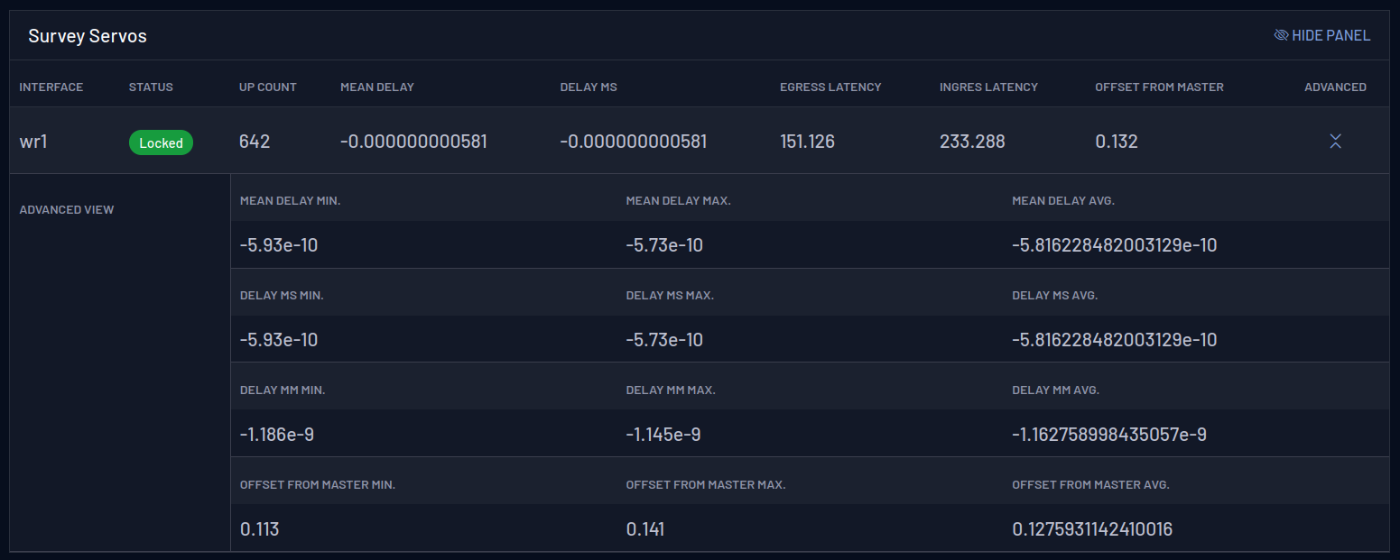
The Survey Servos table reports parameters regarding all interfaces that are not acting as a reference and compares those metrics with the active reference:
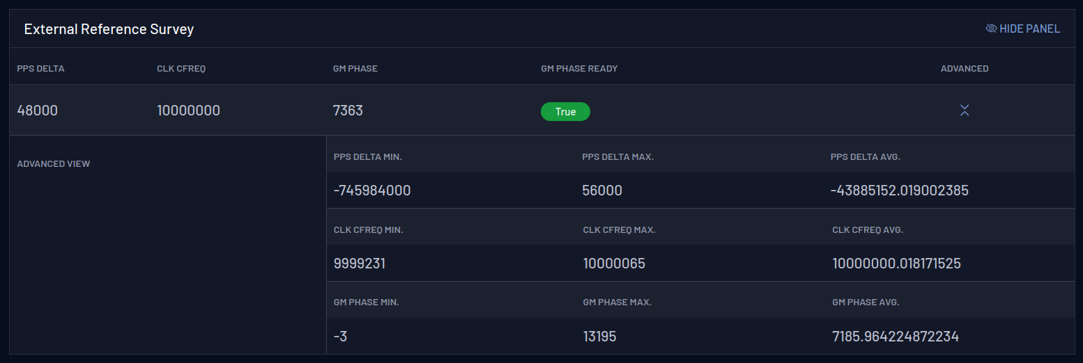
And the External Reference survey table reports data regarding the GM:

WR Survey Mode Configuration
The configuration of the WR survey mode can be accessed by using the Web UI and the CLI configuration.
WR Survey Mode via the Web UI
-
Login into the device dashboard (Editor: link to WebUI section).
-
Navigate to Configuration->Timing General
-
Switch to the Custom profile and configure the timing sources you need in “Time Sources Configuration” section.
-
In “Fanout Configuration” section, configure the interfaces you want in survey mode by selecting “SURVEY” in “Mode” selection box of each interface:

-
Ensure that the “Protocol” selection box marks “WR” in each WR survey interface.
WR Survey Mode via the CLI
-
Open the CLI configuration menu (as explained in (Editor: link to CLI conf))
-
Navigate to “> Timing > Ports Configuration > “
-
For each WR interface to be configured in survey mode, enter to their configuration one by one. Select “WR” in “proto” section, and “SURVEY” in “mode” section:
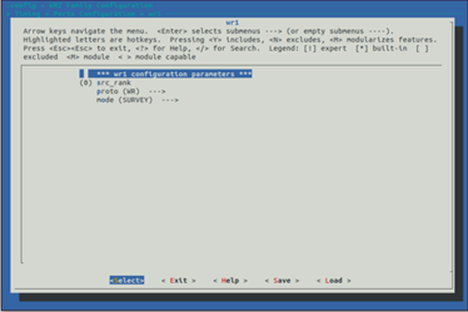
-
Ensure that “src_rank” keeps in the value “0”.
Displaying WR Survey Parameters
Once one or more WR interfaces are configured in survey mode, the user can display the computed timing parameters as if they were an active nominal time source. To view these parameters in the device CLI, use the command:
gpa_ctrl ppsi net/wrX -A
where wrX is the desired survey interface. Once executed, all interfaces parameters are shown.
Some parameters of interest could include:
-
net/wrX/1/servo/mean_delay: Cable round trip time excluding fixed+semistatic (cRTT) -
net/wrX/1/servo/delay_MS: Delay between Master and Slave -
net/wrX/1/servo/delay_MM: The measured round trip time, including fixed+semistatic delays (Legacy WR:'mu') -
net/wrX/1/servo/offset_from_master: The time error between a Slave Clock and a Master Clock (Legacy WR: clock offset)
External Reference (GM) survey mode
The Survey Mode for the external reference, named as Grand Master Survey Mode, is useful to compare an active external reference with a current PTP, NTP, or White Rabbit synchronization.
Configuration of GM Survey mode is done via the CLI or Web GUI.
GM Survey Mode via the CLI
To enable GM survey mode:
-
Open the CLI configuration menu (as explained in (Editor: link to CLI conf))
-
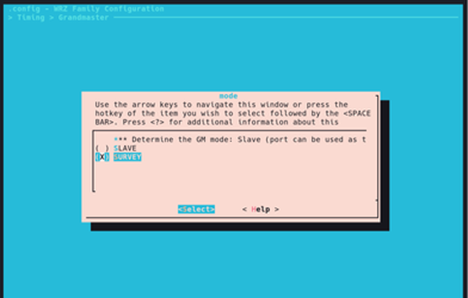
Navigate to Timing > Grandmaster > mode
-
Chose the mode Survey.
-
Reboot the device.
Tip: The device must be set to Boundary Clock mode to use the Survey Mode with an External Reference.
GM Survey Mode via the Web GUI
PPS delta
This allows to measure the time difference between an external PPS signal and the active White Rabbit Reference. When the device is synchronized and has an active PPS reference in frontal panel, the device can measure the actual difference (the delta) between the the internal synchronized and external signal.
Running the gpa_ctrl command: gpa_ctrl hald spll/ext/fpanel/pps_delta will show the such difference, in ps. Here there is an example:
root@z16-014:~# gpa_ctrl hald spll/ext/fpanel
---             hald ---------------------------------------------------------|
   0.8410.1   spll/ext/fpanel/sig_detected         : PPS & CLK
   0.8410.4   spll/ext/fpanel/pps_delta            : -48000               ps
   0.8410.5   spll/ext/fpanel/clk_cfreq            : 10000000             Hz
-
sig_detected: This parameter reports whether both PPS and CLK 10 MHz is connected in the frontal panel. -
pps_delta: This parameter report the delta between PPS signals mentioned before. -
clk_cfreq: This parameter reports the measure of frequency of the 10 MHz input.
A PPS signal in the input (which has been detected by the sig_detected parameter) is mandatory to have a valid pps_delta.
10 MHz reference
The gm_phase reports the phase difference between the external 10 MHz signal and the internal clock, with a resolution of up to 16 ns.
To enable this feature, is mandatory that the device is configured as a Boundary Clock (BC) and has an active 10 MHz input reference. Once the device is locked, the survey_mode for this signal have to be enabled.
Once all the requirements are met, the phase can be read using the command gpa_ctrl hald spll/survey. For example:
root@z16-014:~# gpa_ctrl hald spll/survey
---             hald ---------------------------------------------------------|
   0.8500.1   spll/survey/gm_phase                 : 10913                ps
   0.8500.2   spll/survey/gm_phase_ready           : 1
-
gm_phase: Phase difference between the external 10 MHz reference and the internal clock. -
gm_phase_ready:Defines if thegm_phasevalue is ready to be read.