Monitoring LEDs
The status of the WR-ZEN device can be quickly verified using the 3 visible LEDs in the front-panel. The tables below detail the behavior of each LED depending on the status of the WR-ZEN.
The blinking behavior of the front panel LEDs is represented by the “Visual” column in the following tables using a sequence of three consecutive instants.
General Status
This LED is mainly used to inform the state of the system itself (Daemons loaded, Fans, power-supply, Temperature, CPU load, Available space, etc.).
This led is also used to identify the various stages and modes of the booting procedure.
Status LED behavior
| Visual | Behavior | Description |
|---|---|---|
| 1 ● ● ● 0 ● ● ● |
Steady Green | Device system state is OK |
| 1 ● ● ● 0 ● ● ● |
Steady Red | Device system state is CRITICAL: user might login to verify the source of error. The device might reboot itself if the error is persistent. |
| 1 ● ● ● 0 ● ● ● |
Steady Red & Green | Device system state is WARNING |
| During booting procedure | ||
| 1 ● ● ● 0 ● ● ● |
1x Blinking Green | Bootloader initialization OK |
| 1 ● ●● 0 ● ● ● |
[1-15]x Blinking Red & Green | Reset button is held during the booting procedure:
- If released: entering recovery mode - If hold > 15s: entering reset factory mode |
| 1 ● ● ● 0 ● ● ● |
Steady Red | Device is booting in recovery mode |
| 1 ● ● ● 0 ● ● ● |
Steady Red & Green | Device is booting in reset factory mode |
| 1 ● ● ● 0 ● ● ● |
2x Blinking Green | Booting in normal mode |
| 1 ● ● ● 0 ● ● ● |
Idle | Device is loading kernel and transitioning between modes |
| 1 ● ● ● 0 ● ● ● |
3x Blinking Green | FPGA initialization OK |
| 1 ● ● ● 0 ● ● ● |
Steady Red & Green | The hald daemon has been loaded and it is waiting till all daemons are properly loaded |
| 1 ● ● ● 0 ● ● ● |
Nx Blinking Red & Green | Device is loading in failsafe mode and for each module skipped during initialization the device blinks in orange |
SFP Ports
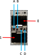
The network ports of the device are arranged in a dual stack SFP cage. The following table represents only the two first ports but can be extrapolated to the other ones. The LEDs of these SFP ports are slightly different to standard usage as it does not differentiate TX/RX but utilizes the arrows to indicate the upper/lower port and their corresponding states:
Ports LED behavior
| Visual | ID | Behavior | Description | |
|---|---|---|---|---|
|
0 | wr0 | wr0 corresponds to upper SFP in the stack | |
| B | ▲ | Link down | When link is down led B is disabled | |
| ▲ | Link up | When link is up the led B stays in green | ||
| D | ▲ | Activity | Blinks in orange each time a packet is received on this port | |
| 1 | wr1 | wr1 corresponds to lower SFP in the stack | ||
| A | ▼ | Activity | Blinks in orange each time a packet is received on this port | |
| C | ▼ | Link down | When link is down led C is disabled | |
| ▼ | Link up | When link is up the led C stays in green | ||