Front panel
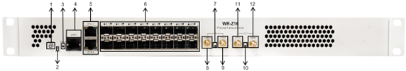
WR-Z16 front panel
Front Panel Legend
| # | Name | Information | Ref. | |||||
|---|---|---|---|---|---|---|---|---|
| #1 | Power button  |
Power On/Off the device | ||||||
| #2 | Reset Button | Button used to perform a factory reset or enter the recovery/failsafe mode | Recovery Mode | |||||
| #3 | Status LED | Green, Orange, Red | System Status | |||||
| #4 | 1x Management UART (RJ45) | Serial UART RS232 on a RJ45 connector with pinout (USB-RJ45/RS232 adaptor not included) |
Logging from the UART | |||||
|
||||||||
| #5 | 2x Management Ethernet (RJ45) | 10/100/1000 ethernet network interface (eth0 & eth1) | Product Specifications | |||||
| #6 | 16x SFP Fiber ports | 1Gbps SFP compatible | White RabbitIEEE 1588-2008 (PTPv2) | |||||
| Timing input | ||||||||
| #7 | Timing Input LED | OK: Green; Warning: Yellow; Critical: Red | Timing Output | |||||
| #8 | 10 MHz input |
● SMA connector (F) |
External Reference (GM) | |||||
| #9 | PPS input |
● SMA connector (F) |
External Reference (GM) | |||||
| Timing output | ||||||||
| #10 | Timing Output LED | OK: Green; Warning: Yellow; Critical: Red | Timing Input | |||||
| #11 | PPS output |
● SMA connector (F) |
Virtual Clock Overview | |||||
| #12 | 10 MHz output |
● SMA connector (F) |
Virtual Clock Overview | |||||