Monitoring LEDs
The status of the WR-Z16 device can be quickly verified using the 3 visible LEDs in the front-panel. The tables below detail the behavior of each LED depending on the status of the WR-Z16.
The blinking behavior of the front panel LEDs is represented by the “Visual” column in the following tables using a sequence of three consecutive instants.
System Status
This LED is mainly used to inform the state of the system itself (Daemons loaded, Fans, power-supply, Temperature, CPU load, Available space, etc.). This led is also used to identify the various stages and modes of the booting procedure.
Status LED behavior
| Visual | Behavior | Description |
|---|---|---|
| ● ● ● | Steady Green | Device system state is OK. There is no Warning or Critical alert. |
| ● ● ● | Steady Red | There is a Warning or Critical alert related to the device. User might login to verify the source of the alert. |
| During booting procedure | ||
| ● ● ● | 1x Blinking Green | Bootloader initialization OK |
| ● ● ● | [1-15]x Blinking Yellow | Reset button is held during the booting procedure:
- If released: entering recovery mode - If hold > 15s: entering reset factory mode |
| ● ● ● | Steady Red | Device is booting in recovery mode |
| ● ● ● | Steady Yellow | Device is booting in reset factory mode |
| ● ● ● | 2x Blinking Green | Booting in normal mode |
| ● ● ● | Idle | Device is loading kernel and transitioning between modes |
| ● ● ● | 3x Blinking Green | FPGA initialization OK |
| ● ● ● | Steady Yellow | The hald daemon has been loaded and it is waiting till all daemons are properly loaded |
| ● ● ● | Nx Blinking Yellow | Device is loading in failsafe mode and for each module skipped during initialization the device blinks in orange |
Timing Output
This LED is used to summarize the timing state (see Timing) of the device and if the user should expect to receive a PPS out from SMA connector according to the configuration of PPS Mode. Blinking behavior in this context refers to blinking continuously at 1Hz in parallel to the PPS output of the device.
Timing Output LED behavior
| Visual | Behavior | Description |
|---|---|---|
| ● ● ● | Blinking Green | Device timing state OK |
| ● ● ● | Blinking Yellow | Device timing state WARNING and the device is LOCKED to an active time source |
| ● ● ● | Blinking Red | Device timing state CRITICAL and PPS mode is ‘Always ON’ |
| ● ● ● | Steady Yellow | Device timing state is in a transitional WARNING. The device is not locked to a reference. |
| ● ● ● | Steady Red | Device timing state CRITICAL and PPS mode is ‘Only Locked’ |
| ● ● ● | Idle | The time manager module has not been loaded yet |
Timing Input
The timing input LED is mainly used to quickly visualize the status of the external reference timing source (see External Reference (GM)) and the detection of PPS/10MHz inputs on the front-panel. Blinking behavior in this context refers to blinking continuously at 1Hz in parallel to the PPS output of the device.
Timing Input LED behavior
| Visual | Behavior | Description |
|---|---|---|
| ● ● ● | Blinking Green | GM is locked, PPS and CLK signals are detected |
| ● ● ● | Blinking Yellow | GM is locked but PPS is not detected (PPS is configured as not mandatory) |
| ● ● ● | Blinking Red | The device is locking to its GM source. PPS & CLK on front panel are detected |
| ● ● ● | Steady Red | In a locking process with its GM source. The device lost the PPS signal or PPS & CLK signal at the same time on front panel |
| ● ● ● | Blinking Yellow | GM preset is active. PPS on front panel is detected. |
| ● ● ● | Idle | GM is not active and PPS on front panel is not detected |
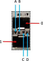
SFP Ports
The network ports of the device are arranged in a dual stack SFP cage. The following table represents only the two first ports but can be extrapolated to the other ones. The LEDs of these SFP ports are slightly different to standard usage as it does not differentiate TX/RX but utilizes the arrows to indicate the upper/lower port and their corresponding states:
Ports LED behavior
| Visual | ID | Behavior | Description | |
|---|---|---|---|---|
|
0 | wr0 | wr0 corresponds to upper SFP in the stack | |
| B | ▲ | Master / Disabled | Led B is disabled if this port is providing timing to other equipment (master mode) or disabled | |
| ▲ | Active slave | Led B is green when port is the active slave that discipline the device | ||
| ▲ | Passive slave | Led B is orange when port is in passive/monitoring mode (§5.1) | ||
| D | ▲ | Link down | When link is down led D is disabled | |
| ▲ | Link up | When link is up the led D stays in green | ||
| ▲ | Activity | Blinks in orange each time a packet is received on this port | ||
| 1 | wr1 | wr1 corresponds to lower SFP in the stack | ||
| A | ▼ | Link down | When link is down led A is disabled | |
| ▼ | Link up | When link is up the led A stays in green | ||
| ▼ | Activity | Blinks in orange each time a packet is received on this port | ||
| C | ▼ | Master / Disabled | Led C is disabled if this port is providing timing to other equipment (master mode) or disabled | |
| ▼ | Active slave | Led C is green when port is the active slave that discipline the device | ||
| ▼ | Passive slave | Led C is orange when port is in passive/monitoring mode | ||