General Timing Management
To ease the configuration of the device the WRZ-OS implements presets to allow a quick setup of the timing sources and of the master ports to redistribute time.
Note: If the device has been shipped with the holdover option, this timing source will be, by default, configured as the last timing source independently of the preset.
Note: PTP Master configuration: Presets only configure the role and protocol (PTP or WR) used for all network interfaces with some default settings. A specific configuration of PTP (e.g., Profile, packet rates, etc.) can then be performed under the PTPv2 configuration tab if a valid license has been detected.
Presets
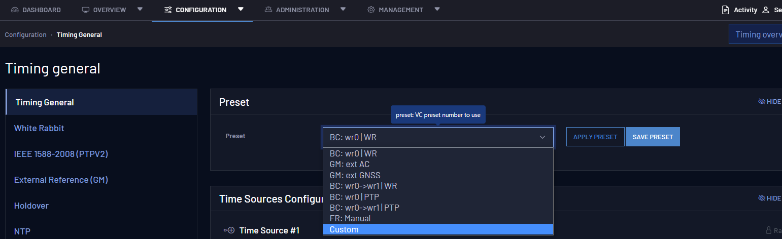
Preset configuration is found in the Web GUI under Configuration > Timing General > Preset.
WR Slave @ wr0 (BC) [default]
Web GUI selection: BC: wr0 | WR
- The primary timing source is provided using WR protocol through interface wr0.
- The other (wr1) is configured as WR master.
This is the default preset as it is the standard/legacy configuration of most of the WR devices. This is the simplest Boundary Clock behavior where the device is disciplined by a single reference and forwards its timing to the down layers through all the other ports.
External Atomic Clock (GM)
Web GUI selection: GM: ext AC
- The primary timing source is provided using an external atomic clock reference through the front-panel 10 MHz and 1PPS inputs (Grand-Master).
- All timing ports (i.e., wr0-wr1
- Clock accuracy is announced below or equal to 25 nanoseconds.
- Alignment of PPS_in VS PPS_out must be done manually (within picoseconds)
- PPS only needed at startup
It is recommended to use this preset when the device is configured to be the Grand-Master in the timing network and is disciplined using an Atomic Clock as external reference.
Here, Atomic Clocks means that a very stable oscillator based on hyperfine transition (e.g, Caesium) that provides very low daily uncertainties (e.g., 1 ns/day) is combined with a GNSS receiver to remove its slow drift using averaging methods. For telecom, this combination is also known as ePRTC and typically provides a UTC representation accurate within 10 ns or less. Moreover, in order to guarantee the best timing performance (phase noise & determinism) the automatic alignment of the PPS output onto the PPS input has been disabled.
Caution: 10 MHz + PPS signal calibration: When using this preset, the PPS must always keep the same delay in respect to the 10 MHz signal. The user can use the GM Offset field to compensate this fixed delay.
External GNSS Receiver (GM)
Web GUI selection: GM: ext GNSS
- The primary timing source is provided using an external GNSS receiver reference through the front-panel 10 MHz and 1PPS inputs (Grand-Master).
- All SFP ports (i.e., wr0-wr1) are configured as WR masters.
- Clock accuracy is announced below or equal to 100 nanoseconds.
- Alignment of PPS_in VS PPS_out is done automatically (adding ~50ps of uncertainties).
- PPS_in is mandatory to announce a valid time.
It is recommended to use this preset when a third-party GNSS is providing the reference to the Grand-Master device. This preset will also ensure the automatic alignment of the PPS input to the PPS output after each time the GNSS locked itself.
Caution: GNSS PPS output: The GM can lock to the PPS from the GNSS receiver before GNSS signal locked (before its 10MHz are locked in phase to its PPS). This causes a jump in the time reference. To avoid this situation, the user should configure the GNSS to not output any PPS before locking to GNSS signals.
Note: Inform GNSS status via PPS: This preset enforces a continuous detection of the PPS input. This means that if the GNSS receiver is configured to disable its PPS when it unlocks (e.g., signal lost), the Grand-Master will then automatically degrade itself as a Free-Running Grand-Master (see VSC-10102 in Grand Master (GM VCS Code)).
External Atomic Clock (GM) / PTP
Web GUI selection: GM: ext AC | PTP
- The primary timing source is provided using an external atomic clock reference through the front-panel 10 MHz and 1PPS inputs (Grand-Master).
- All timing ports (i.e., wr0-wr1
- Clock accuracy is announced below or equal to 25 nanoseconds.
- Alignment of PPS_in VS PPS_out must be done manually (within picoseconds)
- PPS only needed at startup
It is recommended to use this preset when the device is configured to be the Grand-Master in the timing network and is disciplined using an Atomic Clock as external reference.
Here, Atomic Clocks means that a very stable oscillator based on hyperfine transition (e.g, Caesium) that provides very low daily uncertainties (e.g., 1 ns/day) is combined with a GNSS receiver to remove its slow drift using averaging methods. For telecom, this combination is also known as ePRTC and typically provides a UTC representation accurate within 10 ns or less. Moreover, in order to guarantee the best timing performance (phase noise & determinism) the automatic alignment of the PPS output onto the PPS input has been disabled.
Caution: 10 MHz + PPS signal calibration: When using this preset, the PPS must always keep the same delay in respect to the 10 MHz signal. The user can use the GM Offset field to compensate this fixed delay.
External GNSS Receiver (GM) / PTP
Web GUI selection: GM: ext GNSS | PTP
- The primary timing source is provided using an external GNSS receiver reference through the front-panel 10 MHz and 1PPS inputs (Grand-Master).
- All SFP ports (i.e., wr0-wr1
- Clock accuracy is announced below or equal to 100 nanoseconds.
- Alignment of PPS_in VS PPS_out is done automatically (adding ~50ps of uncertainties).
- PPS_in is mandatory to announce a valid time.
It is recommended to use this preset when a third-party GNSS is providing the reference to the Grand-Master device. This preset will also ensure the automatic alignment of the PPS input to the PPS output after each time the GNSS locked itself.
Caution: GNSS PPS output: The GM can lock to the PPS from the GNSS receiver before GNSS signal locked (before its 10MHz are locked in phase to its PPS). This causes a jump in the time reference. To avoid this situation, the user should configure the GNSS to not output any PPS before locking to GNSS signals.
Note: Inform GNSS status via PPS: This preset enforces a continuous detection of the PPS input. This means that if the GNSS receiver is configured to disable its PPS when it unlocks (e.g., signal lost), the Grand-Master will then automatically degrade itself as a Free-Running Grand-Master (see VSC-10102 in Grand Master (GM VCS Code)).
WR Slave @ wr0 > wr1 (BC)
Web GUI selection: BC: wr0->wr1|WR
- The primary timing source is provided using WR through interface wr0. It can failover to a secondary timing source provided using WR through interface wr1.
- All ports except for wr0 and wr1 are configured as WR masters.
This preset provides multi-source redundancy by allowing to configure the two first optical ports as possible timing sources. This means that in case of failure of the first port (i.e., wr0), the device will automatically switch to wr1 as it is configured as secondary source.
PTP Slave @ wr0 > wr1 (BC)
Web GUI selection: BC: wr0->wr1|PTP (PTP)
- The primary timing source is provided using PTP though interface wr0. It can failover to a provided secondary timing source using PTP through interface wr1.
- All ports except wr0 and wr1 are configured as PTP slaves.
This preset provides multi-source redundancy by configuring the two first optical ports as possible timing sources. In case of failure of the first port (i.e., wro), the device will automatically switch to wr1, as it is configured as a secondary source.
WR Slave @ wr0 / PTP Fan-Out
Web GUI selection: BC: wr0|PTP
- The primary timing source is provided using WR protocol through interface wr0.
- All ports except wr0 and wr1 are configured as PTP slaves.
This preset targets devices used as last hop with PTP. The primary timing source is provided using WR protocol through interface wr0. The other port is configured as IEEE 1588-2008 (PTPv2) masters to distribute timing to 3rd party devices.
WR Slave @ wr0>wr1 / PTP Fan-Out
Web GUI selection: BC: wr0->wr1|PTP
- The primary timing source is provided using WR through interface wr0. It can failover to a secondary timing source provided using WR through interface wr1.
- All ports except wr0 and wr1 are configured as PTP slaves.
This preset targets critical devices used as last hop with PTP. The primary timing source is provided using WR through interface wr0. It can failover to a secondary timing source provided using WR through interface wr1.
Manual Free-Running
Web GUI selection: FR: Manual
- The primary timing source is the free running internal oscillator in the device.
- All SFP ports (i.e., wr0 & wr1) are configured as WR masters.
- The device announces itself as a Free-running GM using arbitrary timescale (ARB).
This preset is useful for laboratory and test networks where each node is disciplined by the same free-running oscillator. Selecting this preset will also silence the possible warnings in devices of the down-layers and will preclude the use of the holdover as it cannot learn from a free-running oscillator.
Caution: It is highly recommended to avoid integrating a Manual Free-Running device to a timing network in production as in some corner cases the BMCA/FOCA algorithms might select this timing source when it is not the expected choice.
Custom
The Custom Preset has been designed to allow unique selections for timing source and fanout settings in order to meet any kind of user needs. If the user needs a specific combination that mixes WR on some ports and PTP/IEEEE-1588 or NTP on others, he/she first select the Custom preset and then configure each interface.
Custom Preset via the Web GUI
To configure a custom preset:
-
After logging in to the Web GUI, navigate to Configuration > Timing General > Preset. Select Custom from the drop down menu.
-
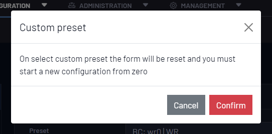
You will be given a warning prompt to acknowledge that your current preset settings (both Time Sources Configuration and Fanout Configuration) will be deleted from the form:
-
Modify each Timing Source in the Timing Source Configuration panel in the order they should be evaluated by the FOCA algorithm. If the Type field is left DISABLED, it will not be evaluated.
The Timing Source Type options are DISABLED, WR, GM, and FR/HO. Selections in the Type field will determine available selections in the Name field.
If you need to reorder your entries, the Rank can be adjusted here as well. To do so, use the blue rank-altering buttons for each timing source.
-
Modify each Fanout Source in the Fanout Configuration panel. The fanouts are listed by order of interface name.
Set the Protocol field to determine the communication method used for that interface. The Protocol field options are DISABLED, WR, PTP, and NTP. If an interface is left as DISABLED, no timing information will be output by that interface. The Mode field options will be determined by selections in the Protocol field.
-
After entering your information, select the Save Configuration button in the lower right of the window. (In order to test functionality, you may select Apply Configuration instead. This setting will not be persistent across reboots unless the configuration is also saved and the unit is rebooted).
You will see a save confirmation banner and a warning that the saved changes will not be applied until the next reboot.
-
Once you have made your desired changes, you can either select the Reboot button from the warning banner, or navigate to Management > Maintenance and select the device Reboot button.
Custom Preset via the CLI
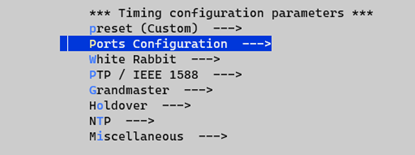
Note: CLI and Custom Preset: The steps to follow in wrz_config (CLI) are slightly different than in the web as it is needed to select the Custom Preset to bring up the corresponding subset of parameters to the menu. If the Custom preset is not chosen in advance, these parameters will stay hidden and thus not configurable.
As shown in Custom Preset with CLI tool, the user first needs to select the preset=Custom to reveal the Ports Configuration submenu and other parameters.
Then each port can be configured independently with:
- Protocol: WR, PTP, NTP, Disabled
- Role: Master, Slave, Auto , Survey
- Source Rank: [0-255], Order the timing source given the source rank priorities where:
- 1 is the first source to be executed and 255 the last one.
- If the source rank is set to 0, the port will not be included as a timing source.
This parameter is not used when the port role is Master.
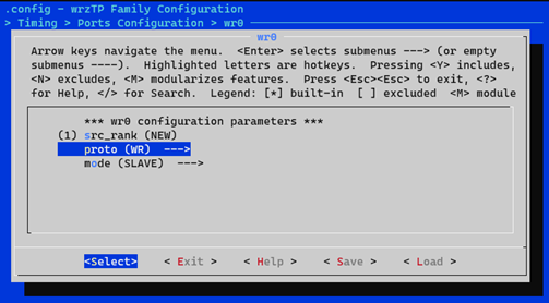
Port configuration (e.g., wr0) from CLI tool
PTP Slave @ wr0 (BC) / PTP
Web GUI selection: BC: wr0 (PTP) | PTP
- The primary timing source is provided using PTP through interface wr0.
- All ports except wr0 are configured as PTP slaves.
Reference topology
The following figure summarizes how devices can be configured with different presets to operate on a generic timing network. To improve the comprehensibility of the reader, this reference topology has been separated in several theoretical layers:
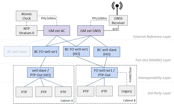
Reference topology with different presets.
- External Reference Layer: It includes the devices that will be fed by several external references (in grey), such as an Atomic Clock or a GNSS receiver, and will receive ToD (Time of Day) from an NTP server (external or embedded). These devices will act as Grand-Master (GM) in the timing network and their timing information will be forwarded to all the timing nodes.
- The Fan-Out Layer or Middle Layer: The devices in this layer are mainly dedicated to spread (fan-out) the timing synchronization to more devices on the down layers. In order to ensure continuous operation, they can be configured with redundant timing sources (e.g., BC FO wr0-wr1) or could incorporate the Holdover option (e.g., BC wr0 slave HO).
- The interoperability Layer: The devices that belong to this layer are also known as last-hop devices. Typically, one of these devices is placed per rack cabinet and is in charge of distributing the ultra-accurate timing provided by the White Rabbit network to other 3rd party devices in the cabinet via PTP, via 10MHz/PPS (legacy devices), etc.
Note: This reference topology is a simplified version of a real timing network and the proposed structure in layers might not be respected: A last-hop device could be connected directly to the GM or an external GNSS reference could be used as backup in the fan-out/interoperability layer.
Note: Some devices in the reference topology strategically include the holdover option (HO) to ensure continuous operation even if not locked to any timing sources. This option is automatically enabled if detected and the provided presets can be used without any modifications.
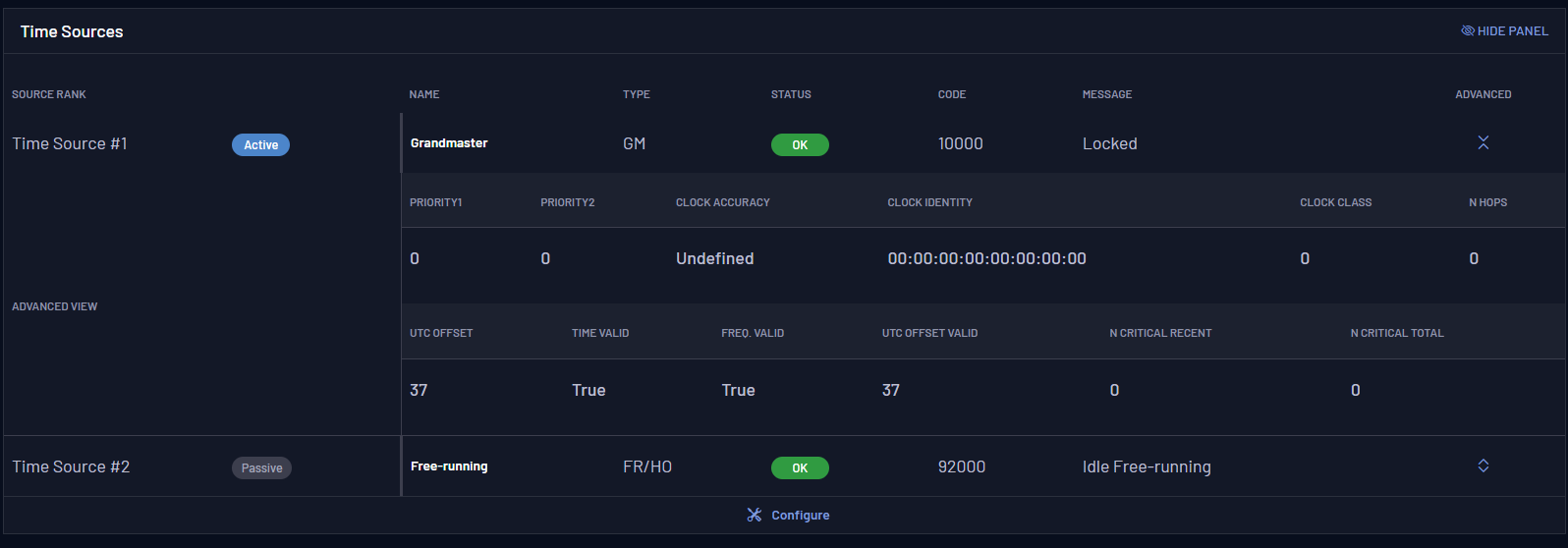
Timing source info
Each timing source shares a common set of values processed by the strategy in order to decide how to discipline the virtual clock of the device.
By navigating to Overview > Timing Overview the user will be able to quickly understand the state of all timing sources.The figure below shows the parameters related to the primary (#1) timing source.

The parameters contained in the previous table are described as follows:
| OID | Name | Value | Description |
|---|---|---|---|
| 3.13x0.x | tsrc_info/x/xxx | Information about the x timing source. | |
| 3.13x0.1 | Name | <String> (i.e., wr0, front-panel, eth1, etc.) | Name of the corresponding timing source. |
| 3.13x0.2 | Type | GM WR PTP HO/FR |
Type of timing source, each type can have slightly different state machines to properly handle its timing source. |
| 3.13x0.3 | VCS Code | <Integer> | Code defined in the VSC table (VCS Code) that corresponds to a given condition for this timing source. |
| 3.13x0.4 | Status | Disabled OK Warning Critical |
Status that corresponds to the code defined in the VSC table. |
| 3.13x0.5 | Message | <String> | Message that corresponds to the code defined in the VCS table. |
| 3.13x0.6 | Is Active | <Boolean> | Flag that indicates if this timing source has been selected by the policy to actively discipline the virtual clock of our device. |
The timing source can be expanded to show its advanced view by clicking on the up-down icon under Advanced:
The advanced view parameters are described below:
Timing source info description
| OID | Name | Value | Description |
|---|---|---|---|
| 3.13x1.xx | tsrc_info/x/Q | Clock Quality of the x timing source. | |
| 3.13x1.1 | Clock Identity | <String> | Unique identity of PTP instance in the network. |
| 3.13x1.2 | Priority1 | <Integer>
Default: 128 |
Force BMCA decision using 1st priority (Lower values take precedence). |
| 3.13x1.3 | Priority2 | <Integer>
Default: 128 |
Manually force BMCA to select a clockID when clock quality is the same (Lower values take precedence). |
| 3.13x1.10 | Clock Class | <Integer>
Default: 248 |
The Clock Class is one of the attributes that characterizes the timing source. |
| 3.13x1.11 | Clock Accuracy | <Enum> | It indicates the expected accuracy of the timing source. It shall be conservatively estimated based on the time source. |