+1.585.321.5800
IRIG In/Out [1204-05, -27]
The IRIG Input/Output option card provides SecureSync with one IRIG input and two IRIG outputs. The IRIG input can be used as the primary SecureSync time and 1PPS reference input for synchronization. Or, it can also be used in conjunction with other primary references (such as GNSS and NTP) to synchronize SecureSync. Available with BNC or Fiber Optic ST connectors.
IRIG In/Out, BNC [1204-05]: Input Specifications
- Input Signal: IRIG A, B, G or NASA-36;
amplitude modulated sine wave (AM) OR pulse-width-coded (DCLS); user-selectable, with automatic switching of load on input - AM Carrier: IRIG B 1000 Hz, IRIG A 10 kHz and G 100 kHz
- AM Signal Level: 500 mV to 10 Vp-p (modulated 2:1 to 6:1); 50 Ω load
- DCLS Signal Level: TTL; 0.8V max., 2.3V min fail.; >10 kΩ load
- Connector: AM and DCLS: BNC female
- Accuracy: n/a
- Number of Cards: Up to 6
- Ordering Information: 1204-05, IRIG module, BNC Connector
IRIG In/Out, BNC [1204-05]: Output Specifications
- Output Signal: IRIG A, B, G, E, H, or NASA-36, amplitude modulated sine wave (AM), 0.5V to 6Vp-p into 50 Ω; or pulse-width-coded (DCLS). User-selectable.
- AM Carrier: IRIG B 1000 Hz, IRIG A and G 100 or 100
- AM Signal Level: 500 mV to 10 Vp-p [high Z]; (modulated 2:1 to 6:1).
- DCLS Signal Level: >10 kΩ TTL
- Connector: AM and DCLS: BNC female
- Accuracy: see IRIG Output Accuracy Specifications
- Number of Cards: Up to 6
- Ordering Information: 1204-05, IRIG module, BNC Connector

Model 1204-05 option card rear plate
IRIG In/Out, Fiber Opt. [1204-27]: Input Specifications
- Signal: IRIG A, B, G or NASA-36, (DCLS only, unmodulated)
- Operating Wavelength: 820/850 nm
- Optical Minimum Sensitivity: -25 dBm @ 820 nm
- Fiber Optic Compatibility: 50/125 μm, 62.5/125 μm multi-mode cable
- Optical Connector: ST
- Accuracy: n/a
- Number of Cards: Up to 6
- Ordering Information: 1204-27, IRIG module, Fiber Optic ST Connector
IRIG In/Out, Fiber Opt. [1204-27]: Output Specifications
- Signal: IRIG A, B, E, G or NASA-36, (DCLS only, unmodulated)
- Operating Wavelength: 820/850 nm
- Optical Power: -15 dBm average into 50/125 fiber
- Fiber Optic Compatibility: 50/125 μm, 62.5/125 μm multi-mode cable
- Optical Connector: ST
- Accuracy: see IRIG Output Accuracy Specifications
- Number of Cards: Up to 6
- Ordering Information: 1204-27, IRIG module, Fiber Optic ST Connector
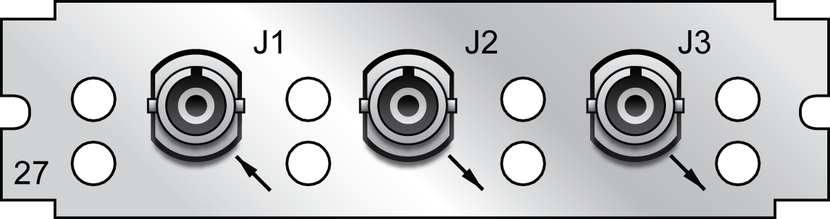
Model 1204-27 option card rear plate
Supported IRIG Formats
The IRIG option cards models 1204-05 and -27 support IRIG input and output formats A, B, and G (DCLS). IRIG-E is also available as an output, and the 1204-05 card supports A, B, E, G, and H AM formats (see the following tables). Additionally, the cards support inputs with frequency/resolution values of no carrier/index count interval, 1kHz/1ms, 10 kHz/0.1 ms, and 100 kHz/10 ms, as well as IRIG input coded expressions of the fields BCDTOY, CF, SBS, and BCDYEAR.
The IRIG inputs support the following coded expression combinations for BCDTOY, CF, SBS, and BCDYEAR fields:
- 0 – BCDTOY, CF, SBS
- 1 – BCDTOY, CF
- 2 – BCDTOY
- 3 – BCDTOY, SBS
- 4 – BCDTOY, BCDYEAR, CF, SBS
- 5 – BCDTOY, BCDYEAR, CF
- 6 - BCDTOY, BCDYEAR
- 7 - BCDTOY, BCDYEAR, SBS
The cards support synchronization with the following DCLS IRIG input formats:
| Provided DCLS IRIG Code Format |
Code Description |
|---|---|
|
A-DCLS |
|
| A000 | IRIG A, DCLS, BCDTOY, CF, SBS |
| A001 | IRIG A, DCLS, BCDTOY, CF |
| A002 | IRIG A, DCLS, BCDTOY |
| A003 | IRIG A, DCLS, BCDTOY, SBS |
| A004 | IRIG A, DCLS, BCDTOY, BCDYEAR, CF, SBS |
| A005 | IRIG A, DCLS, BCDTOY, BCDYEAR, CF |
| A006 | IRIG A, DCLS, BCDTOY, BCDYEAR |
| A007 | IRIG A, DCLS, BCDTOY, BCDYEAR, SBS |
|
B-DCLS |
|
| B000 | IRIG B, DCLS, BCDTOY, CF, SBS |
| B001 | IRIG B, DCLS, BCDTOY, CF |
| B002 | IRIG B, DCLS, BCDTOY |
| B003 | IRIG B, DCLS, BCDTOY, SBS |
| B004 | IRIG B, DCLS, BCDTOY, BCDYEAR, CF, SBS |
| B005 | IRIG B, DCLS, BCDTOY, BCDYEAR, CF |
| B006 | IRIG B, DCLS, BCDTOY, BCDYEAR |
| B007 | IRIG B, DCLS, BCDTOY, BCDYEAR, SBS |
|
E-DCLS (output only) |
|
| E000 | IRIG E, DCLS, BCDTOY, CF, SBS |
| E001 | IRIG E, DCLS, BCDTOY, CF |
| E002 | IRIG E, DCLS, BCDTOY |
| E003 | IRIG E, DCLS, BCDTOY, SBS |
| E004 | IRIG E, DCLS, BCDTOY, BCDYEAR, CF, SBS |
| E005 | IRIG E, DCLS, BCDTOY, BCDYEAR, CF |
| E006 | IRIG E, DCLS, BCDTOY, BCDYEAR |
| E007 | IRIG E, DCLS, BCDTOY, BCDYEAR, SBS |
|
G-DCLS |
|
| G001 | IRIG G, DCLS, BCDTOY, CF |
| G002 | IRIG G, DCLS, BCDTOY |
| G005 | IRIG G, DCLS, BCDTOY, BCDYEAR, CF |
| G006 | IRIG G, DCLS, BCDTOY, BCDYEAR |
| H-DCLS (1204-05 card only, output only) | |
| H002 | IRIG-H, DCLS, BCDTOY |
|
NASA-36 |
|
| NASA-36 | NASA-36, DCLS, 10 msec |
Accepted IRIG reference formats
The 1204-05 card also supports the following analog IRIG inputs.
| Provided AM IRIG Code Format |
Code Description |
|---|---|
|
A-AM |
|
| A130 | IRIG A, AM, 10kHz, BCDTOY, CF, SBS |
| A131 | IRIG A, AM, 10kHz, BCDTOY, CF |
| A132 | IRIG A, AM, 10kHz, BCDTOY |
| A133 | IRIG A, AM, 10kHz, BCDTOY, SBS |
| A134 | IRIG A, AM, 10kHz, BCDTOY, BCDYEAR, CF, SBS |
| A135 | IRIG A, AM, 10kHz, BCDTOY, BCDYEAR, CF |
| A136 | IRIG A, AM, 10kHz, BCDTOY, BCDYEAR |
| A137 | IRIG A, AM, 10kHz, BCDTOY, BCDYEAR, SBS |
|
B-AM |
|
| B120 | IRIG B, AM, 1kHz, BCDTOY, CF, SBS |
| B121 | IRIG B, AM, 1kHz, BCDTOY, CF |
| B122 | IRIG B, AM, 1kHz, BCDTOY |
| B123 | IRIG B, AM, 1kHz, BCDTOY, SBS |
| B124 | IRIG B, AM, 1kHz, BCDTOY, BCDYEAR, CF, SBS |
| B125 | IRIG B, AM, 1kHz, BCDTOY, BCDYEAR, CF |
| B126 | IRIG B, AM, 1kHz, BCDTOY, BCDYEAR |
| B127 | IRIG B, AM, 1kHz, BCDTOY, BCDYEAR, SBS |
|
E-AM (output only) |
|
| E110 | IRIG E, AM, 100 Hz, BCDTOY, CF, SBS |
| E111 | IRIG E, AM, 100 Hz, BCDTOY, CF |
| E112 | IRIG E, AM, 100 Hz, BCDTOY |
| E113 | IRIG E, AM, 100 Hz, BCDTOY, SBS |
| E114 | IRIG E, AM, 100 Hz, BCDTOY, BCDYEAR, CF, SBS |
| E115 | IRIG E, AM, 100 Hz, BCDTOY, BCDYEAR, CF |
| E116 | IRIG E, AM, 100 Hz, BCDTOY, BCDYEAR |
| E117 | IRIG E, AM, 100 Hz, BCDTOY, BCDYEAR, SBS |
| E120 | IRIG E, AM, 100 Hz, BCDTOY, CF, SBS |
| E121 | IRIG E, AM, 1 kHz, BCDTOY, CF |
| E122 | IRIG E, AM, 1 kHz, BCDTOY |
| E123 | IRIG E, AM, 1 kHz, BCDTOY, SBS |
| E124 | IRIG E, AM, 1 kHz, BCDTOY, BCDYEAR, CF, SBS |
| E125 | IRIG E, AM, 1 kHz, BCDTOY, BCDYEAR, CF |
| E126 | IRIG E, AM, 1 kHz, BCDTOY, BCDYEAR |
| E127 | IRIG E, AM, 1 kHz, BCDTOY, BCDYEAR, SBS |
|
G-AM |
|
| G141 | IRIG G, AM, 100kHz, BCDTOY, CF |
| G142 | IRIG G, AM, 100kHz, BCDTOY |
| G145 | IRIG G, AM, 100kHz, BCDTOY, BCDYEAR, CF |
| G146 | IRIG G, AM, 100kHz, BCDTOY, BCDYEAR |
| H-AM (1204-05 card only, output only) | |
| H122 | IRIG-H, AM, 1KHz, BCDTOY |
|
NASA-36 |
|
| NASA-36 | NASA-36, AM, 1 msec |
Additional IRIG reference formats for 1204-05
IRIG Output: Signal State
To quickly view if an IRIG output is enabled, or disabled, navigate to the option card’s Status Summary panel. For instructions, see: Viewing an Input/Output Signal State.
IRIG Input: Edit Window
To configure the IRIG Input (also referred to as ‘Reference’), navigate to its Edit window. For instructions, see: Configuring Option Card Inputs/Outputs.
The Web UI list entries for these cards are: IRIG In/Out BNC and IRIG In/Out Fiber.
The connector number is: J1.
Note: SecureSync starts numbering I/O ports with 0 (only 1PPS and 10 MHz outputs start at 1, because of the built-in outputs).
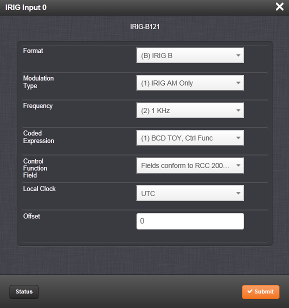
The Edit window allows the configuration of the following settings:
- Format: Sets the formatting of the IRIG input signal, as defined by the IRIG generator time source. The available choices are:
- IRIG A
- IRIG B
- IRIG G
- NASA-36
- Modulation Type: Configures the type of input signal modulation. The choices are:
- IRIG DCLS—A TTL (Phase) modulated signal.
- IRIG AM—An amplitude modulated signal.
- Frequency: The IRIG modulation frequency. This is determined by the configuration of Format and Modulation Type. See IRIG Carrier Frequencies for details.
- Coded Expression—Defines the data structure of the IRIG signal, where:
- BCD = Binary Coded Decimal
- TOY = Time of Year
- CF = Control Field
- SBS = Straight Binary Seconds
- The available options will vary according to the configurations of Format and Modulation Type.
- Control Function Field: IRIG signals have an optional section in the data stream that can be used to include additional information (such as the present year, for example). This field allows the Control Field section of the IRIG output to be defined. The available configurations are:
- Fields conform to RCC 200-04: IRIG spec 200-04 specified a location for year value, if included in this field.
- Fields conform to IEEC 37.118-2005 (IEEE 1344): Control Field contains year, leap second and daylight savings time information.
- Fields conform to Spectracom Format: Year is included in Control Field but not in the same location as RCC-2004 output (year is offset by one position).
- Fields conform to Spectracom FAA Format: A unique IRIG output Control Field that contains satellite lock status and time error flags.
- Fields conform to NASA Formats: Variants of IRIG B
- Fields confirm to Spectracom IEEE C37.118-2005: Has been extended to support one-month leap second notification
The available options will vary according to the configurations of Format and Modulation Type.
Note: If the Format value is changed, the Control Field and Coded Expression change to the default values for the given Format value. The user can only change the Control Field field and Coded Expression field to allowed values for the Format field.
It is recommended that the SecureSync administrator/operator only use this if they do not know what the IRIG Input Format is, and they wish to identify the signal type, or to determine if a signal is present.
- Local Clock: The incoming IRIG input time information may be provided as local time, but System Time may be configured as UTC time, so internal computations need to be performed. With the Timescale field set to “Local”, select the name of a previously created Local Clock. The Time Zone and DST rules, as configured in the Local Clock will be applied to the front panel time display.
- Offset: Provides the ability to account for IRIG cable delays or other latencies in the IRIG input. The Offset value is entered and displayed in nanoseconds (ns). The available Offset range is -500 to +500 ms.
Configuring the IRIG Input Year
The IRIG time source may be able to provide SecureSync with the current year information via the IRIG input data stream. As the year value is not a required field in the IRIG data stream, (and if the year value is present, it may not always be in the same location of the Control Field), if the year value is contained in the control field section of the IRIG data stream, the control field “layout” needs to be defined in SecureSync (as determined by the Coded Expressions and Control Field values). If the year value is not present in the IRIG input signal, the year value will need to be manually set in SecureSync when using IRIG input as the only input Time reference.
Note: By default, the “year” fields in the IRIG message are ignored and a user-defined value is used.
Note: By default, the “year” fields in the IRIG message are ignored and a user-defined value is used. Make sure the year is set correctly when the SecureSync is installed. If the year is not set correctly before NTP achieves time synchronization, it will use the value entered. The unit will also default to the year entered if it is powered down during the rollover of the year. If the SecureSync was not switched on during the rollover, this value must be updated.
Note: When the IRIG Input year is updated, NTP must be restarted from the Web UI NTP page (or the SecureSync unit rebooted) for the New Year value to take effect.
The current year value can be manually entered from the MANAGEMENT/OTHER/Time Management page. The year value only needs to be manually entered once, as it will automatically increment to the next year each New Year’s day. See System Time for instructions on how to set the current year manually.
Verifying IRIG Input Signal Validity
See: Verifying the Validity of an Input Signal.
IRIG Input: Status Window
To view the current settings of the IRIG Input (also referred to as ‘Reference’), go to its Status window. For instructions, see: Viewing Input/Output Configuration Settings.
The Web UI list entries for these cards are: IRIG In/Out BNC and IRIG In/Out Fiber. The connector number is: J1.
Note: SecureSync starts numbering I/O ports with 0 (only 1PPS and 10 MHz outputs start at 1, because of the built-in outputs). .
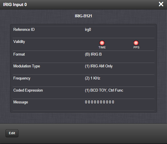
The Status window displays the following settings:
- Reference ID: If you have only one IRIG card installed, SecureSync will number that card 0 and it will be identified as irg0. Additional cards will be numbered irg1 or above.
- Validity: If the IRIG input is not present, or is not considered valid and qualified, the “1PPS Validity” and “Time Validity” fields will be considered “Not Valid” (Orange).

- Once the IRIG input has been supplied and the signal is considered valid and qualified, the two indicators will then turn “Valid” (Green).
- Format: Identifies the formatting of the IRIG input signal, as defined by the IRIG generator time source. The possible values are:
- IRIG A
- IRIG B
- IRIG G
- NASA-36
- Modulation Type: Identifies the type of input signal modulation. The possible values are:
- IRIG DCLS—A TTL (Phase) modulated signal.
- IRIG AM—An amplitude modulated signal.
- Frequency—The IRIG modulation frequency. This is determined by the configuration of Format and Modulation Type. See also: IRIG Carrier Frequencies.
- Coded Expression: Defines the data structure of the IRIG signal, where:
- BCD = Binary Coded Decimal
- TOY = Time of Year
- CF = Control Field
- SBS = Straight Binary Seconds
- Message: The IRIG message.
IRIG Output: Edit Window
To configure the settings of one of the two IRIG Outputs, go to its Edit window. For instructions, see: Configuring Option Card Inputs/Outputs.
The Web UI list entries for these cards are: IRIG In/Out BNC and IRIG In/Out Fiber.
The connector numbers are: J2 and J3.
Note: SecureSync starts numbering I/O ports with 0 (only 1PPS and 10 MHz outputs start at 1, because of the built-in outputs). .
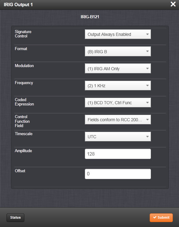
The Edit window allows the configuration of the following settings:
- Signature Control: Is used to control when the IRIG modulation will be present. This function allows the modulation to stop under certain conditions; see also Signature Control.
- Format: Used to configure the desired IRIG output formatting. The available choices are:
- IRIG A
- IRIG B
- IRIG G
- IRIG E
- NASA-36
- Modulation: Changes the type of output signal modulation. The available choices are:
- IRIG DCLS—A TTL-modulated output.
- IRIG AM-–An amplitude modulated output. The amplitude of the output is determined by the value entered in the Amplitude field.
- Frequency—The IRIG modulation frequency. This is determined by the configuration of Format and Modulation Type. See also IRIG Carrier Frequencies.
- Coded Expression: Defines the data structure of the IRIG signal, where:
- BCD = Binary Coded Decimal
- TOY = Time of Year
- CF = Control Field
- SBS = Straight Binary Seconds
- The available options will vary according to the values of Format and Modulation Type.
- Control Function Field: IRIG signals have an optional section in the data stream that can be used to include additional information (such as the present year, for example). This field allows the Control Field section of the IRIG output to be defined. The available configurations are:
- Fields conform to RCC 200-04: IRIG spec 200-04 specified a location for year value, if included in this field.
- Fields conform to IEEC 37.118-2005 (IEEE 1344): Control Field contains year, leap second and daylight savings time information.
- Fields conform to Spectracom Format: Year is included in Control Field but not in the same location as RCC-2004 output (year is offset by one position).
- Fields conform to Spectracom FAA Format: A unique IRIG output Control Field that contains satellite lock status and time error flags.
- Fields conform to NASA Formats: Variants of IRIG B
- Fields confirm to Spectracom IEEE C37.118-2005: Has been extended to support one-month leap second notification
The available options will vary according to the configurations of Format and Modulation Type.
- Timescale: Used to select the time base for the incoming time code data. The entered Timescale is used by the system to convert the time in the incoming data stream to UTC time for use by the System Time. The available choices are:
- UTC—Coordinated Universal Time ("temps universel coordonné"), also referred to as ZULU time
- TAI—Temps Atomique International
- GPS—The raw GPS time as transmitted by the GNSS satellites (as of -, this is 18 seconds ahead of UTC time).
- A local clock set up through the Time Management Page—This option will appear under the name of the local clock you have set up. See Local Clock(s), DST for more information. Local timescale allows a Local Clock to apply a time offset for Time Zone and DST correction.
- Amplitude: The peak-to-peak output voltage level into a 600 Ω load is adjusted by entering a digital control value in this field. The level adjustment has no effect on TTL outputs, only on AM formats. The value of 128 will cause the Mark amplitude to be about 5Vp-p into high impedance. A value of 200 results in an output amplitude of about 9Vp-p into high impedance.
Note: These are nominal values only. Actual values will vary from unit to unit. To adjust the level precisely, connect an oscilloscope to the output connector when adjusting.
- Offset: Provides the ability to account for IRIG cable delays or other latencies in the IRIG input. The Offset value is entered and displayed in nanoseconds (ns). The available Offset range is -500 to +500 ms.
For IRIG frequency and output specifications, see IRIG Standards and Specifications.
IRIG Output: Status Window
To view the current settings of one of the IRIG Outputs, go to its Status window. For instructions, see: Viewing Input/Output Configuration Settings.
The Web UI list entries for these cards are: IRIG In/Out BNC and IRIG In/Out Fiber. The connector numbers are: J2 and J3.
Note: SecureSync starts numbering I/O ports with 0 (only 1PPS and 10 MHz outputs start at 1, because of the built-in outputs).
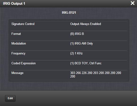
The Status window displays the following settings:
- Signature Control: is used to control when the IRIG modulation will be present. This function allows the modulation to stop under certain conditions; see also Signature Control.
- Format: Used to configure the desired IRIG output formatting. The possible values are:
- IRIG A
- IRIG B
- IRIG G
- IRIG E
- NASA-36
- Modulation: Changes the type of output signal modulation. The possible values are:
- IRIG DCLS—A TTL-modulated output.
- IRIG AM-–An amplitude modulated output. The amplitude of the output is determined by the value entered in the Amplitude field.
- Frequency—The IRIG modulation frequency. This is determined by the configuration of Format and Modulation Type. See also: IRIG Carrier Frequencies.
- Coded Expression: Defines the data structure of the IRIG signal, where:
- BCD = Binary Coded Decimal
- TOY = Time of Year
- CF = Control Field
- SBS = Straight Binary Seconds
- The possible values will vary according to the values of Format and Modulation Type
- Message: The IRIG message of the output.
For IRIG frequency and output specifications, see IRIG Standards and Specifications.