Configurable Connectors
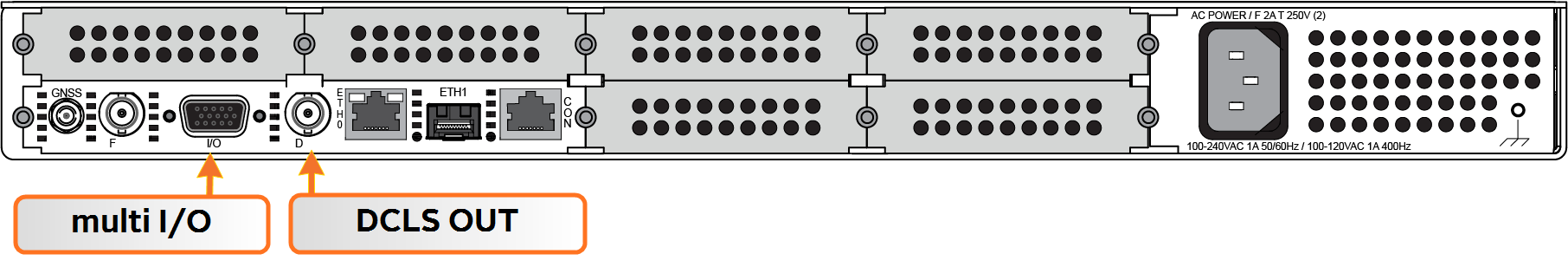
This Section covers the two software-configurable connectors on the CPU board (rear panel): the BNC DCLS OUT connector and the HD15 multi I/O connector.
When you configure an input our output via the DCLS OUT connector or the I/O connector, you will need to adjust both the pin configuration (Assigning Signals) and (for some types) the settings for that input or output via the Web UI (Configuring Input References and Configuring Outputs).
You can find the settings for signals currently configured through these two connectors under INTERFACES > OPTION CARDS > Main. The CPU board with the standard-issue connectors is referred to as "Option Card 0" in the Web UI.
BNC DCLS OUT
The DCLS Out connector can be configured with the following options. See Assigning Signals for detailed instructions.
DCLS Output Options
| Location | Available Signal Types | Web UI Selection | |
|---|---|---|---|
| DCLS OUT | BNC Connector (rear Panel) |
1PPS Output (default) | PPS_OUT | DCLS_TTL |
| IRIG Output | IRIG_OUT | DCLS_TTL | ||
| HaveQuick Output | HQ_OUT | DCLS_TTL | ||
| GPIO Output | GPIO_OUT | DCLS_TTL |
DB15 Multi I/O
Note on the table below: Both RS485 connectors have optional termination on their inputs. To select this feature, choose the Web UI feature as listed below that also includes With Termination in the listing.
Multi I/O Input and Output Options
| Pin Location | Available Signal Types | Web UI Selection | |
|---|---|---|---|
| DCLS OUT | Pin 6 (signal) Pin 7 (ground) |
1PPS Output | PPS_OUT | DCLS_TTL |
| IRIG Output (Default) | IRIG_OUT | DCLS_TTL | ||
| HaveQuick Output | HQ_OUT | DCLS_TTL | ||
| GPIO Output | GPIO_OUT | DCLS_TTL | ||
| DCLS IN | Pin 1 (signal) Pin 2 (ground) |
1PPS Input | PPS_IN | DCLS_TTL |
| IRIG Input (Default) | IRIG_IN | DCLS_TTL | ||
| HaveQuick Input | HQ_IN | DCLS_TTL | ||
| RS232 IN | Pin 15 (signal) Pin 10 (ground) |
ASCII Time Code Input (Default) | ATC_IN | RS232 |
| RS232 OUT | Pin 5 (signal) Pin 10 (ground) |
ASCII Time Code Output (Default) | ATC_OUT | RS232 |
| RS485 (#1) | Pin 3 (signal) Pin 13 (signal) Pin 8 (ground) |
1PPS Output | PPS_OUT | RS485 |
| IRIG Output | IRIG_OUT | RS485 | ||
| HaveQuick Output (Default) | HQ_OUT | RS485 | ||
| ASCII Time Code Output | ATC_OUT | RS485 | ||
| 1PPS Input | PPS_IN | RS485 | ||
| IRIG Input | IRIG_IN | RS485 | ||
| HaveQuick Input | HQ_IN | RS485 | ||
| ASCII Time Code Input | ATC_IN | RS485 | ||
| RS485 (#2) | Pin 4 (signal) Pin 14 (signal) Pin 9 (ground) |
1PPS Output | PPS_OUT | RS485 |
| IRIG Output | IRIG_OUT | RS485 | ||
| HaveQuick Output | HQ_OUT | RS485 | ||
| ASCII Time Code Output | ATC_OUT | RS485 | ||
| 1PPS Input | PPS_IN | RS485 | ||
| IRIG Input | IRIG_IN | RS485 | ||
| HaveQuick Input (Default) | HQ_IN | RS485 | ||
| ASCII Time Code Input | ATC_IN | RS485 | ||
| IRIG AM Output | Pin 11 (signal) Pin 12 (ground) |
IRIG AM Output (Default, non-configurable) | |
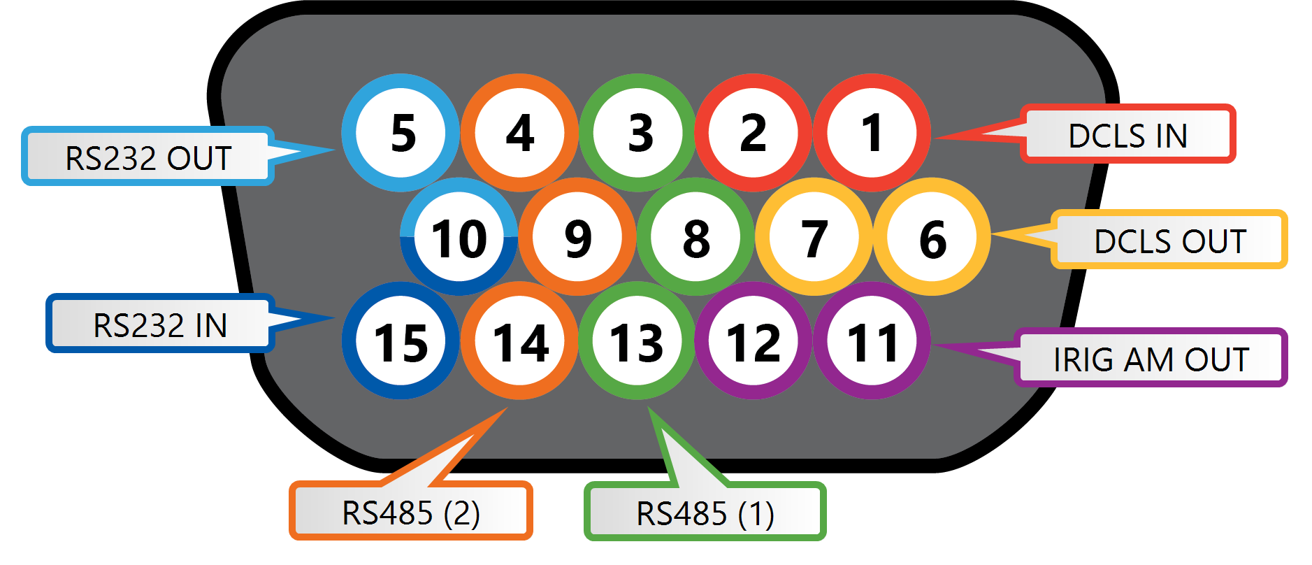
Multi I/O 15-pin connector, in mating direction from front
| Pin | Signal |
|---|---|
| 1 | DCLS IN |
| 2 | GND |
| 3 | (First signal) RS485 A, non-inverting |
| 4 | (Second signal) RS485 A, non-inverting |
| 5 | RS232 TX OUT |
| 6 | DCLS OUT |
| 7 | GND |
| 8 | GND |
| 9 | GND |
| 10 | GND |
| 11 | IRIG AM OUT |
| 12 | GND |
| 13 | (First signal) RS485 B, inverting |
| 14 | (Second signal) RS485 B, inverting |
| 15 | RS232 RX IN |
Assigning Signals
Changing the signals on either the rear panel BNC DCLS connector, or on the Multi I/O 15-pin connector requires access to the Web UI.
- In the SecureSync Web UI, navigate to MANAGEMENT > NETWORK: Pin Layout. The Pin Layout screen will be displayed.
- View your current pin layout settings in the Layout panel. The pins are grouped together by their channels (see the Multi I/O 15-pin connector, in mating direction from front). One pin in each channel will update the settings for the entire channel.
- To change a signal, you can Delete it, but you may also simply assign the new signal as described below, thus overwriting the existing Input or Output.
- Add a pin configuration by clicking the PLUS icon in the top-right corner. The Add Pin popup window will display.
- Start with the Type Filter drop-down menu (second line in the window) and select a signal type.
- From the Signal drop-down menu, select a signal.
- From the Pins drop-down menu in line 3, select the pin set you wish to configure.
- Click Submit.
-
In the Actions panel, click Apply Changes after all your configuration is done. This button will finalize your changes and force a server reboot (some timing sources may be affected by this change).
SecureSync is shipped with a default I/O configuration that you can be customized. However, if required you can restore the default configuration at any time after applying changes.
To restore the default I/O pin configuration:
- Navigate to the MANAGEMENT: NETWORK > Pin Layout screen.
- In the Actions panel on the left, click Restore Default Layout.
To reload the currently used I/O configuration after adding pin layout changes, but before clicking Apply Changes:
- Navigate to the MANAGEMENT: NETWORK > Pin Layout screen.
- In the Actions panel on the left, click Reload Layout.
Before you perform a clean upgrade or restore your unit's default settings, you can choose to download your current pin layout settings.
(Note: The Save Layout option applies only to the pin configuration for the DCLS BNC connector and the 15-pin I/O connector. To save your entire configuration including these settings, see Backing-up and Restoring Configuration Files.)
- To save the current layout, navigate to the MANAGEMENT > NETWORK > Pin Layout screen.
- In the Actions panel, click the Save Layout button to download a file containing your current settings.
- Save this file in a location of your choosing and perform any necessary actions.
- To restore your former layout, click the Upload Layout button in the Pin Layout screen.
- Choose the name and location of the file saved when using the Save Layout function. Click the Upload button.